
DIN or AGD
Gages can conform to either standard. Which are right for your application?


George Schuetz
When selecting a dial indicator for range, resolution and size, it may be important to consider the standards to which it was made.


A longtime friend of mine from Russian once told me that eventually the U.S. would use the metric system as a standard—and that we would get there “one inch at a time.” While we are not a metric country yet, the manufacturing industry tries to be international, and that often means producing parts in metric units. Certainly most of the automotive industry has moved to this system. As parts and manufacturing processes are moved around the world, it’s becoming more and more common to see gages made to different standards—for example, DIN standards from Germany/Europe or JIS standards from Japan.
In the U.S., most gaging specifications are documented to AGD (American Gage Design) standards and published under ANSI/ASME (American National Standard Institute/American Society of Mechanical Engineers).
For most of Europe, gages are designed and built to DIN standards (German Institute for Standardization and the German ISO member). These standards cover more than just German products, as DIN is a member of the European Committee for Standardization (CEN), an umbrella organization covering 30 EU members that utilize DIN specifications.
So what’s the big deal whether a gage—let’s say a caliper—is an ASME design or a DIN-compliant design? To the user, it usually doesn’t matter much. There may be a difference in how or if performance specs are defined, or in how the product is calibrated. There are, however, some products that are physically different in both design and philosophy of use depending on whether they are based on AGD or DIN standards. A few that come to mind include dial indicators, master rings and discs that differ in both their physical shape and how they measure.
Whether you are receiving a new gaging solution from another country or looking through the catalogs of gage suppliers with world presence, it does not hurt to have a basic knowledge of the differences among some of these products. We will start with dial indicators and take a look at some other products over the next few months.
General Use and Philosophy
All dial indicators are basically mechanical amplifiers. Through gearing, they take a linear motion and amplify it to a rotating hand that allows you to “see” the displacement. How this mechanical amplifier is packaged and tested is what the specifications are all about.
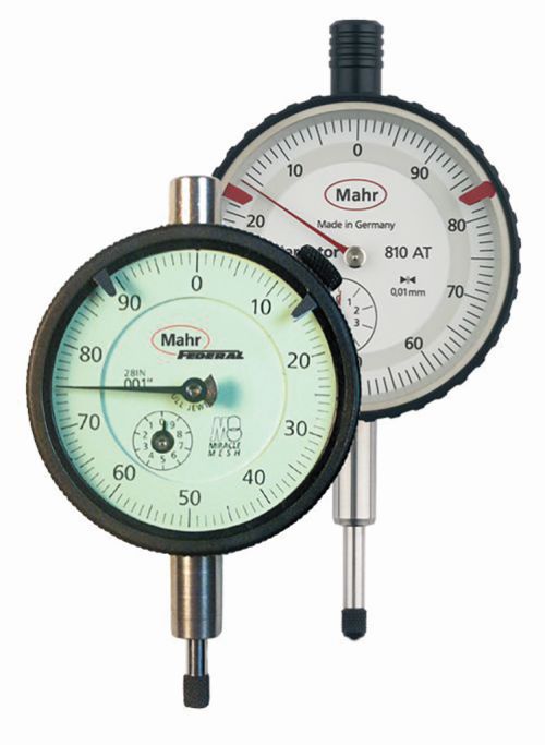
U.S. (ASME) dial indicators are primarily used for comparative purposes in a bench gage or stand to compare a part’s measured value to a master. Thus, they more commonly have a balanced dial with a plus sign to the right to indicate a larger size. Dial indicators are available in various configurations and with longer ranges for certain measuring applications. They are also commonly furnished with a lug back or alternate back for fixture mounting.
DIN indicators are slightly different as, in most cases, the operator is using them to determine if parts are within allowable tolerances. They are typically furnished with continuous faces and rev counters, and have longer measuring ranges.
Sizes
Dial indicators are available in numerous outside diameter sizes that may be determined by use (portable or bench-mounted) and how far the customer is from the reading.
AGD/ANSI calls out five standard sizes:
• Group 0: 1.25-inch diameter (32 mm)
• Group 1: 1.75-inch diameter (44 mm)
• Group 2: 2.25-inch diameter (57 mm)
• Group 3: 2.75-inch diameter (70 mm)
• Group 4: 3.625-inch diameter (92 mm)
DIN, on the other hand, specifies that the indicator must fall within a certain size range, e.g., 55-60 mm. Most suppliers will thus provide an indicator with a 58-mm diameter but also offer other sizes such as 34-mm, 50-mm or 108-mm.
Because the Group 2 AGD/ANSI indicator is fairly close to the DIN 58-mm, they are interchangeable in most protective housings designed for either indicator.
Stem Diameters and Accessories
It is in the stem diameters and accessories that the differences are more pronounced. AGD/ANSI inch indicators use a 0.375-inch stem mounting and a 4- to 48-inch thread for the contact. DIN specifies an 8-mm stem and an M2,5 metric thread.
Mounting an indicator by the stem can cause some frustration. With an adapter, it’s simple to mount a DIN indicator into a gage designed for an AGD/ANSI. But attempting to mount an AGD indicator into a DIN gage is more difficult. It may be easier to get the indicator in with an 8-mm stem (either style) rather than trying to change mounting arms.
Resolution
Indicators are available in inch or metric units, regardless of what standard they are built to, and you obviously will want one that matches the units to which you are measuring. And while they may not offer the same resolution, they are fairly close in their displacement. Once you understand some of the differences between their design basics, you can choose the style that best fits your needs.


Read Next

3 Mistakes That Cause CNC Programs to Fail
Despite enhancements to manufacturing technology, there are still issues today that can cause programs to fail. These failures can cause lost time, scrapped parts, damaged machines and even injured operators.
Read More

The Cut Scene: The Finer Details of Large-Format Machining
Small details and features can have an outsized impact on large parts, such as Barbco’s collapsible utility drill head.
Read More