Electronic Height Gages
We've looked at "basic" comparative height gages, which are used for layout tasks and other surface plate measurements. Related to these are instruments known as electronic height gages.
We've looked at "basic" comparative height gages, which are used for layout tasks and other surface plate measurements. Related to these are instruments known as electronic height gages. These offer a high degree of flexibility and functionality so that, in addition to lab-based work, they are useful as production gages. In quality departments, they are used for first part and incoming inspections and layout work, while on the shop floor, they are used be machinists for checking features on one-off parts.
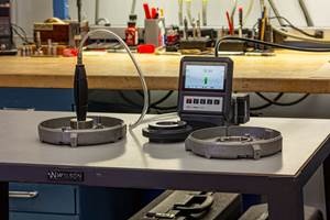
The key features of the electronic height gage are a probe that senses when the part is touched; a glass or capacitance scale that tracks the probe's height; and a readout/control unit. Many also incorporate a motor drive to position the probe. There are a base and a body, to maintain the components in a stable, rigid relationship, and to accurately position the scale perpendicular to the surface plate on which the gage rests. And often, there is an internal pump that generates a thin cushion of air beneath the base, allowing the gage to be moved around easily on the surface plate.
Glass and capacitance scales have gotten so good that these gages are reliable enough for shop-floor use, and so accurate over a long range as to blur the lines between comparative and absolute gaging. Most height gages can measure in both modes and even toggle between them on a single measurement. Resolution of 0.0001 inch/0.001 mm, with accuracy of 0.0005 inch/0.013 mm over a range of 24 inches/615 mm is common, while high-end instruments offer resolution down to 10 microinches/0.5 micrometers and accuracy of 0.00012 inch/0.0025 mm.
Two sensing technologies predominate: touch triggers and active probes. Both types can be set to trigger from both downward and upward touches. Once these points are collected, it's easy to calculate the difference between them, for either inside measurements (such as slot lengths and widths, and inside diameters) or outside measurements (such as ODs or thicknesses). One can also average the two readings to find hole centers or center lines. From there, it's an easy step to calculate distances between centers.
The more common touch triggers send a signal to the scale only once per touch. Active probes, found on higher-end systems, constantly update their positions, and record the positions once they reach a stable reading on the part.
Active probes have the potential to generate more accurate diameter measurements, because the user can tram the gage perpendicularly to the feature's axis, to capture the highest and lowest points on the top and bottom surfaces. (See figure.) To correctly measure a diameter with a touch trigger, a special contact, which is designed to seek the low or high point of the diameter is used.
Even the relatively simple control units associated with touch triggers tend to be highly capable. These are usually programmable for multiple measurement routines, can accept presets, and calculate widths, thicknesses, and distances between centers.
More powerful controllers, which usually accompany active probes, are required for dynamic measurements. These data processors are capable of generating SPC reports, and turning the single-axis height gage into a virtual two-dimension measuring machine.
The gage must be zeroed before measuring parts. This is usually done by touching the probe to the reference surface—usually a surface plate. Gages can also be referenced against a gage block, or against a datum on the workpiece itself.
Before measuring inside or outside dimensions, the diameter of the ball end of the probe must be compensated for. This involves touching the probe to the top and bottom of a special reference artifact. The controller calculates the diameter as the difference between the measured reading and the known distance between the two reference surfaces.
Related Content
4 Ways to Establish Machine Accuracy
Understanding all the things that contribute to a machine’s full potential accuracy will inform what to prioritize when fine-tuning the machine.
Read MoreDetermining Out-of-Roundness at the Point of Manufacture
George Schuetz, Mahr Inc.’s Director of Precision Gages, offers these techniques for measuring roundness on the shop floor.
Read MoreHow To Calibrate Your Calipers
If you’re interested in calibrating your own digital, dial or Vernier calipers, here are some steps to take to make sure it goes off without a hitch.
Read MoreHow to Choose the Correct Measuring Tool for Any Application
There are many options to choose from when deciding on a dimensional measurement tool. Consider these application-based factors when selecting a measurement solution.
Read MoreRead Next
3 Mistakes That Cause CNC Programs to Fail
Despite enhancements to manufacturing technology, there are still issues today that can cause programs to fail. These failures can cause lost time, scrapped parts, damaged machines and even injured operators.
Read MoreThe Cut Scene: The Finer Details of Large-Format Machining
Small details and features can have an outsized impact on large parts, such as Barbco’s collapsible utility drill head.
Read More


.png;maxWidth=300;quality=90)


.png;maxWidth=300;quality=90)

