
Gaging Commutators
Measuring and adjusting critical parameters of these motor devices will help make them function most effectively.


George Schuetz
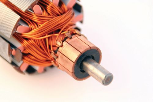
The commutator of a DC motor is a cylindrical structure attached to the motor shaft along with the armature windings.


A DC motor is a device that converts electrical energy to mechanical energy. The conversion essentially happens between two major
parts: the stator, the static part that holds the windings and receives the input power, and the rotor, the rotating part that brings about the
mechanical rotations.
The commutator of a DC motor is a cylindrical structure attached to the motor shaft along with the armature windings. It is made up of copper segments stacked together, but insulated from each other. Its function is to switch the armature current as supplied through the motor’s stationary brushes. This switched current reversal applies power to the rotating shaft and causes the armature shaft to start rotating and continue to rotate as it moves from one switch to the next.
In order to guarantee the effective function of the commutator and ensure best performance, there are critical parameters that must be gaged. These include:
• Roughness, which affects contact between the commutator and the brushes and impacts the wearing/abrasion of the commutator.
• Roundness and run-out of the segments, which are important because uneven gaps, different gap heights and out-of-round surfaces will damage contact between the commutator surfaces and the motor brushes, which will promote spark formation, increase wear and reduce motor performance.
It should be pointed out that there are many other dimensional and geometric relationships happening in the DC motor even before we start checking the commutator, including in the housing that holds the bearings that receive the armature shaft. The dimensional fit between the shaft and the bearings, and between the bearing mounts and the end plates of the motor housing are both dimensionally very critical. Form or dimensional errors can result in slippage on the bearing and premature motor failure.
There also is the geometric relationship between the commutator and the brushes. This is where the rubber meets the road—or, in this case, where the copper meets the brushes, which are carbon or graphite structures that make sliding contact over the rotating commutator. As noted, the brushes provide electric current from outside the motor to the rotating commutator where it goes into the armature winding. This contact between the commutator and the brush unit is really where the power gets transmitted. If there are flaws in how the commutator matches with the brushes, then balance errors or power surges will cause less-than-optimum motor performance.
Special gages have been developed to measure the characteristics of the commutator, as a whole and individually down to the performance of each of its segments. The method of measurement is pretty basic, but it is the analysis of the collected data that determines how well the commutator may perform. In essence, the gaging method for commutators is to rotate the armature shaft assembly on its bearing journals, and measure and collect data on the commutator through one revolution with a high-resolution/fast-response probe.
Of course, the most basic dimension is the size of the commutator, which will determine the forces applied by the brushes. However, since the part is being rotated on the bearing journals, we can also monitor the commutator’s diameter change and concentricity (total indicator runout).
Further and more detailed analysis of the commutator allows us to look at each segment and the relationships between them. Segment gap parameters include:
• Bar to bar
• Delta to bar
• Delta max bar
• Straighten-up delta bar
• Local form defaults
• Delta center of segment
• Segment to segment
• Runout (vee reference)
Each one of these characteristics affects how the current passes from the brush to the commutator land. Even minor imperfections on the mating surfaces reduce the ability of the current to fully power the windings and reduce output power, and improper mating and the resulting gaps cause sparking and premature damage to the brush and armature. Closely monitoring these conditions enables manufacturers of DC motors to get every ounce of power from the product.


Read Next


The Cut Scene: The Finer Details of Large-Format Machining
Small details and features can have an outsized impact on large parts, such as Barbco’s collapsible utility drill head.
Read More
3 Mistakes That Cause CNC Programs to Fail
Despite enhancements to manufacturing technology, there are still issues today that can cause programs to fail. These failures can cause lost time, scrapped parts, damaged machines and even injured operators.
Read More