
Getting the Most from Your Comparator Stand
Paying attention to fine details can help you achieve accurate measurements that otherwise seem impossible.


George Schuetz


The most robust, heavy-duty comparator stands are designed to make measurements down to 20 microinches (0.50 micron) or better. Given the typical shop environment, some may question if this is really possible. The simple answer is “yes,” but it requires diligence and attention to fine detail.
Following is the process for setting up a system and conducting actual measurements using a precision stand with two inductive probes and a high-resolution bench amplifier.
Setup Requirements/Process
Part size and shape will dictate how the bench stand is set up. The appropriate probe type used also will depend on various factors, including part characteristics, operator use of the gage and measurement specifications. Here are the key steps necessary to minimize error in the system:
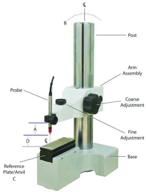
1. Make the distance between the inductive probes as short as possible to minimize mechanical deflection error.
2. Set the upper probe to have a heavier force spring than the lower probe. This helps keep the part against the reference surface (plate).
3. Use two probes to eliminate vibration and out-of-flat conditions. Mount the upper probe body section closest to the contact point. Preset the bottom probe to -0.010 inch (-0.25 mm) or less, then mount it with the block on the anvil and adjust it to zero. The probe should not
protrude more than 0.010 inch (0.25 mm) from the plate surface. Upper and lower probe alignment should be set as close to centerline as possible.
4. Secure the lower anvil/plate and ensure it is square to the probes.
5. Secure the stand arm in its final location. Adjust the arm so that the upper probe reads close to zero against a nominal size block.
6. Lock the fine adjustment. Use the mechanical fine adjustment so the upper probe reads as close to zero as possible when locked.
7. Calibrate the system using three gage blocks that cover the range of sizes to be measured. The larger the range, the larger the potential for error in the system.
When the system is set up and calibrated, it is possible to see repeatability of less than 10 microinches (0.25 micron) when using the proper grade of certified gage blocks. Using gage blocks can prove the system performs to the desired specification. However, even the best setup may not provide good results unless attention is paid to how the measurements are acquired.
Measurement Requirements/Process
The measurement process is a key part of collecting data on the true size of a part. For this system to perform at its best, further details must be considered, including how the measurement is actually conducted, variations in the components used and the actual characteristics being measured. Some elements can be controlled by the care given to the part and its movement, while other elements may have inherent errors that cannot be overcome. Here are the considerations needed to minimize error in the measurement process:
1. Use guides, mark the part, or try a template to ensure repeat positioning.
2. Consider probe contact and hysteresis, which can be a big source of mechanical error. The influence of hysteresis can be reduced by always moving the part in the same direction from first reading through last. Hysteresis can be almost completely eliminated by use of a lifting lever so the probe is never in contact when the part is moved. This may depend on the shape of the part. Alternately, use a pneumatic probe.
3. Minimize human contact with the part and stand components. Use gloves or plastic tools to move the part, and breathe normally, just not on the gage or part.
4. Consider surface roughness, such as Ra and Rz. If the part roughness is 20 microinches (0.50 micron) already, don’t expect the gage to do better.
5. Check or consider that the part top and bottom sides are not parallel.
6. Check the reference plate flatness. The change in part characteristics such as length and thickness play a role as it is moved across the reference plate. The plate itself may also have flatness of 40 microinches (1 micron). Opposing probes eliminate this error from the system. Only the part can introduce error.
7. Act quickly because time is relevant, and the environment is always changing state. Repeatability is influenced by changes in temperature, humidity, handling, cleanliness and more.
As you can see, all the fundamentals of metrology apply. You can’t deny or ignore the laws of physics and expect good results. A bench stand is just one tool that helps get you there—the details are up to you.


Read Next


The Cut Scene: The Finer Details of Large-Format Machining
Small details and features can have an outsized impact on large parts, such as Barbco’s collapsible utility drill head.
Read More
3 Mistakes That Cause CNC Programs to Fail
Despite enhancements to manufacturing technology, there are still issues today that can cause programs to fail. These failures can cause lost time, scrapped parts, damaged machines and even injured operators.
Read More