Here is a quick refresher on the two basic types of surface gaging system. Skid-type, or averaging systems, have a hinged probe assembly in which the probe rides next to a relatively broad skid that also contacts the workpiece. The skid tends to filter out waviness, so the probe measures only short-wavelength variations.
In contrast, skidless gages, or profiling systems, incorporate a smooth, flat internal surface as a reference, so the probe can respond to waviness as well as roughness. These systems tend to be more costly because they require more expensive probe and drive systems and a little more calculating power to perform the complex analysis of separate, long- and short-wavelength variations. Often, however, this cost is virtually mandated by the configuration of the surface.
There are two concerns with valve seats: the length of the land and the roughness of the surface. The most common type of probe used for skidded roughness measurements is the longitudinal probe, which moves the measuring probe coincident with its own axis. The length of the skid from the front of the probe to the center of the stylus is fixed, which means that the measurement surface has to have a minimum length to provide sufficient contact for the skid. If the skid is unsupported, results will be erroneous. In many cases, the length of the valve seat is so short that a skidded probe moving in a longitudinal direction cannot provide reliable results and should not be used.
However, there is another type of skidded probe in which the measuring heads move in a lateral direction. This probe is designed so that the skid runs transverse to the length of the measurement probe. The skid surface is located directly to the left (or right) of the probe, as opposed to in front of the stylus. This type of probe is a good alternative to longitudinal-type probes because the skid length is short and can be used where the measurement land area is short or where the measurement area is close to a shoulder. However, the radius of the skid surface is also small. This is where the probe can have an issue.
When measuring a surface with a short skid radius in the transverse direction, its important to consider peak spacing (Sm) before doing the actual roughness (Ra) value checks. Typically, with machined surfaces the rougher the surface, the greater the peak spacing.
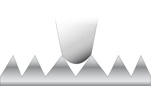
The distances between the peaks of the measurement surface have to be spaced to ensure that the skid does not “fall in between” the peaks. The example shown in Figure 1 shows a measurement probe in which the skid radius is smaller than the peak spacing. If the stylus radius falls between the peaks, mechanical filtering of the roughness values will result in measurement readings that are less than the actual measurement values.
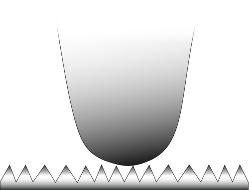
The ideal situation for measuring accuracy, shown in the Figure 2, is to have the skid on the probe sit atop the peaks on the surface of the part. This will ensure that no mechanical filtering of the measurement results occurs. With the skid riding atop the peaks, the stylus will travel the full dimension from the top of each peak to the bottom of each valley. Generally, the skid radius should be at least 50 times greater than the peak spacing on the roughness standard.
For these reasons—minimizing the effects of mechanical filtering as a result of a long skid length on a longitudinal probe, and having a short skid radius when using a lateral-type skidded probe—skidless measurement probes are often recommended for the evaluation of short-land/high-value applications such as valve seats. Because the datum surface on a skidless system is built into the drive unit rather than being placed at the end of the measurement probe, mechanical filtering of the measurement results does not take place, and measurement results are more accurate.