
Simplifying Tricky Sizing Adjustments
When simple arithmetic will not suffice, use custom macro B to calculate more complicated workpiece measurements.
.jpg;width=70;height=70;mode=crop;format=webp)

Mike Lynch


Most sizing adjustments a turning center operator makes are pretty easy, requiring no more than simple addition and subtraction. If a diameter is coming out 0.002-inch too large, the X-axis offset for the cutting tool machining the diameter is reduced by 0.002 inch. Similar techniques are used for length (Z-axis) dimensions.
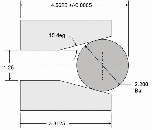
But consider the workpiece shown in the figures on this page. The operator must place a gage ball in the tapered bore and measure workpiece length over the ball. This time, simple arithmetic will not suffice should the dimension need adjustment. Indeed, the taper’s starting X position and ending Z position must be altered, requiring right-angle trigonometry.
The problem is compounded because this dimension has a very tight tolerance. Several sizing adjustments may be required as the cutting tool wears.
You can easily simplify the task of making complex sizing adjustments using custom macro B. Again, we’re showing a specific example, but consider any time when your operators struggle when making sizing adjustments. It is likely that similar techniques can be used.
In our solution, the operator will use a permanent common variable (#501) to specify the deviation from the required dimension (4.5625 inches) to the measured dimension. If the dimension comes out 0.004-inch oversize, the operator will enter 0.004 in permanent common variable #501. If it comes out undersize by 0.003 inch, the operator will enter -0.003. Note that it may be more convenient to use an offset register in which to enter this deviation. If it makes more sense to do so, by all means, do it. Just determine the appropriate system variable number to access the desired offset register.
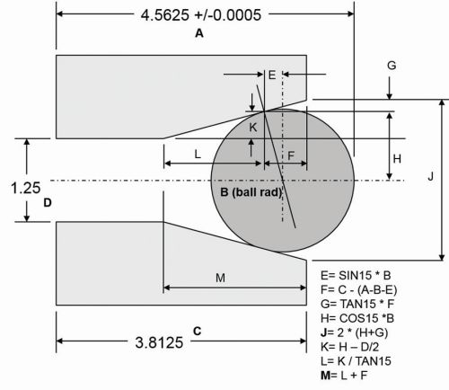
Following is the segment of the custom macro program that handles this issue. Only the finish boring bar commands are shown. You can surely come up with a more elegant way to handle the math, but we’ve made it match the drawings for clarity.
O0001
#502=4.5625-#501 (Distance over ball)
N3 #1= SIN[15]*1.1 (E)
#2= 3.8125 - [#502 - 1.1 -#1] (F)
#3= TAN[15] *#2 (G)
#4= COS[15] * 1.1 (H)
#5= 2 * [#4 + #3] (J)
#6= #4 - 1.25/2 (K)
#7= #6 / TAN[15] (L)
#8= #7 + #2 (M)
T0202 M42
G96 S500 M03
G00 X[#5 +2*TAN[15]*0.1] Z0.1 M08 (0.1 in approach distance)
G01 X1.25 Z-#8 F0.008
Z-4.9
X1.15
G00 Z0.1
X7.0 Z8.0
M30
Again, if the distance over the ball is coming out precisely on size, permanent common variable #501 will be zero. (You must confirm that #501 is set to zero before the production run is started.) If the 4.5625-inch dimension comes out to 4.5635, the operator will enter 0.001 in permanent common variable #501. If it comes out to 4.5613, the operator will enter -0012 in #501. In either case, the custom macro will calculate the appropriate start point in X and end point in Z for the taper move.


