
Taking Advantage Of Sub-Plates On Machining Centers
Sub-plates and component tooling dramatically simplify the hard and fixed task of making workholding setups on machining centers. This kind of tooling can be purchased from standard suppliers or made by your own people.
.jpg;width=70;height=70;mode=crop;format=webp)


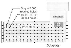
Sub-plates and component tooling dramatically simplify the hard and fixed task of making workholding setups on machining centers. This kind of tooling can be purchased from standard suppliers or made by your own people. One common configuration incorporates a grid of location or clamping holes every 2 inches. Every 2 inches, a 1/2-inch hole may be reamed for location to a depth of 0.5 inch. Every other 2 inches, a tapped hole may be machined for clamping purposes. For holes not currently in use, rubber plugs can be made and inserted to keep chips from getting into the holes. Figure 1 shows an example of a this kind of sub-plate.
Once mounted to the table and aligned, this kind of sub-plate can simplify the placement of component workholding tooling making up the setup. Most users will number each hole (as in Figure 1) so it's very easy to designate into which holes component tools are to be mounted.
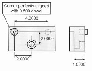
Though this truly simplifies workholding setup, many sub-plate users don't take full advantage of a sub-plate's ability to minimize setup time. If working with this kind of device, you should be able to attain two more important benefits. First, since the holes are on 2-inch centers, the location of program zero should be predictable as long as you are working with accurate component tooling. Look at the corner location component tool drawing (Figure 2). Notice that the upper left location surfaces (program zero surfaces) are perfectly aligned with the dowel hole. If this component tool is placed in hole C4, program zero will be precisely 4 inches from the left-most hole in X and 6 inches from the lowest hole in Y.
If you shift the point of reference for fixture offset entries to the lower left hole, all fixture offset entries can be specified from the lower left hole (as opposed to the zero return position). This will make for predictable program zero assignment values if you use accurate component tooling.
Second, since you're making qualified setups, you can eliminate the task of program zero assignment from setup by including G10 commands in your program to specify the location of program zero. The command N005 G90 G10 L2 P1 X4.0 Y6.0 Z2.5, for example, enters the fixture offset values for a 1.5-inch thick workpiece located from the corner locator placed in hole C4. For Z, we're assuming that you've shifted the point of reference for Z-axis fixture offsets to the top of the sub-plate in the common fixture offset.


