
Standardizing The Measurement Process To Find The Right Gage
Guidelines used to standardize the measuring process can provide a good basis for making gage decisions.


I did some figuring the other day and estimate, conservatively, that we have probably answered at least 50,000 gaging questions over the past 35 years or so. Some of these questions have been challenging. They have pushed me to learn more about my business and our industry, and to grow professionally. Many questions have to do with various “rules of thumb” that have been floating around the industry for ages.
Over the years, much has happened to standardize the measurement process and make it more reliable and repeatable. International, national and industrial organizations have put procedures in place to help ensure that the process—and its verification—is correct and followed every time.


Interestingly, most of these measuring processes are based on old rules that were studied and improved upon and their concepts eventually incorporated into one or more of today’s standards. The thing to remember is that, while these old “rules” may form the basis of today’s practice, they themselves are not necessarily the best practice. But when there is some shopfloor, part-quality disaster going on, referencing some of these basics may save the day.
The granddaddy of them all is the 10-to-1 rule, which most likely came out of early manufacturing, turned into a military standard and then evolved into some of the standards used today. Its basis still makes sense when arriving at those basic setup decisions that put good gages together.
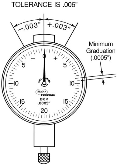
For example, in gages with analog or digital readouts, the rule says the measuring instrument should resolve to approximately one-tenth of the tolerance being measured. This means if the total tolerance spread is 0.0002 inch, the smallest increment displayed on the gage should be 20 microinches. A gage that only reads to 50 microinches can’t resolve closely enough for accurate judgments in borderline cases and doesn’t allow for the observation of trends within the tolerance band. On the other hand, a digital gage that resolves to 5 microinches might give the user the impression of excessive part variation as a lot of digits go flying by when using the display. With that said, 10:1 is not readily achievable on some extremely tight tolerance applications—say, ±50 microinches or less—and it may be necessary to accept 5:1. But for coarse work, 10:1 or something very close to it is always a good recommendation.
Without a doubt, the most common question I am asked has to do with selecting a gage: “I’ve got a bushing with a 0.750-inch bore that has to hold ±0.001 inch. What kind of gage should I use?” There are a number of choices: a dial bore gage, an inside micrometer, an air plug, a self-centralizing electronic plug or any one of several other gages. But picking the right gage for an application depends basically on three things: the tolerance you are working with, the volume of components you are producing and the degree of flexibility you require in the gaging system.
For gage performance, we go back to our 10-to-1 rule: If your tolerance is ±0.001 inch, you need a gage with a performance rating of at least 10 times that, or within one-tenth (±0.0001 inch). A gage repeatability and reproducibility study (GR&R) may be a way of determining the gage performance. GR&R studies are designed to show how repeatable the specified accuracy is when the gage is used by a number of operators measuring a number of parts in the manufacturing environment. There is no single standard for GR&R studies, but generally, it is a statistical approach to quantifying gage performance under real-life conditions. Often this is expressed as the ability to measure within a certain range a certain percent of the time. The gage you pick should pass your own in-house GR&R requirements.
Typically, the rule of thumb for selecting a master has been to choose one whose tolerance is 10 percent of the part tolerance. This, combined with the gage’s performance, should provide adequate assurance of a good measurement process. It’s usually not worthwhile to buy more accuracy than this 10-to-1 rule; it costs more, it doesn’t improve the accuracy, and the master will lose calibration faster. On the other hand, when manufacturing to extremely tight tolerances, you might have to use a ratio of 4:1 or even 3:1 between gage and standard, simply because the master cannot be manufactured and inspected using a 10:1 rule.
These are examples of where a rule of thumb may be the basis for a gage decision. It is not necessarily the final decision, but provides a way of working towards the best choice based on accepted test processes. There are many other rules relating to surface finish checking and gage design, and we’ll look at some of them next.
Additional Guidelines
Previously, we discussed the 10-to-1 rule as it applies to gage performance. It says the gage should perform to a level better than 10 percent of the tolerance. While this rule has mostly been replaced by the more scientific and standardized gage repeatability and reproducibility (GR&R) performance test, other rules of thumb are still in play.
Gage Design
For example, we gage-builders take this 10-to-1 rule a little further. In order to build a gage that performs better than 10 percent of the tolerance in use, we actually need to design a gage that performs to 4 percent of the tolerance with the things we can control: namely the gage components and the master. That’s pretty demanding, but it has a foundation in logic.
That logic comes from our SWIPE principle, in which the measurement process has five parts: the standard (master), the workpiece, the instrument (gage), the people and the environment. We have a chance of controlling two out of the five parts of the process: the master and the instrument. If we can control those two items to achieve 4 percent part tolerance performance, we will achieve the 10 percent measuring process performance. This is where we start when trying to solve a customer’s application.
Part staging establishes the basic relationship between the measuring instrument (typically a dial or digital indicator) and the workpiece. Any error in the fixture inevitably shows up in the measurements. Many fixtures are designed around a C-frame shape and, as such, have a substantial cantilever that is subject to deflection. This problem is greatly reduced if the fixture is a solid one-piece unit.
Most fixtures also consist of a minimum of three pieces—a base, a post and an arm—that must be fastened together with absolutely no play among them, as any movement will be magnified at least tenfold at the workpiece. Play of only a few millionths in a couple of joints can easily accumulate so that measurements to ten-thousandths become unreliable, regardless of the level of discrimination of the instrument. Thus, in designing gage structure, the most simple is often the best.
Surface Parameter Conversion
In today’s global economy, machined parts are being made and shipped around the world. As a result, manufacturing and quality control engineers are often forced to decide whether or not to accept a part when the print requirements are not consistent with measurement results of the surface gages at the local facility. Some quality control engineers simply assume that if a part is checked and passed using the local parameter available, the part will also pass other checks.This assumes that a constant correlation, or ratio, exists between different parameters.
This assumption is true, to a point: there are rules of thumb that can be used to convert Ra to Rz or Rz to Ra. Using a ratio range for Rz to Ra between 4-to-1 and 7-to-1 is a safe conversion. However, if the manufacturer uses Ra but the customer uses Rz, then the conversion ratio would be much higher, possibly as high as 20-to-1. Also, the actual shape of the part’s profile will have a significant impact on these ratios.
Communication at the outset of the project can avoid most surprises. Approximate and sometimes questionable comparisons can be avoided with an understanding of exactly what a parameter on a print means and how the various parties involved in the production plan to check surface texture.
Air Versus Contact Gaging
The response of air to surface finish, however, is more complicated. Think of a jet of air. The measurement “point” is really the average area of the surface the jet is covering. Now consider the finish, or roughness, of that surface. The measurement point of the air jet is actually the average of the peaks and valleys the jet is exposed to (see illustration). This is not the same measurement you would have if a contact-type probe was used. This difference is a source of real gaging error, one that is most often apparent when two different inspection processes are used.
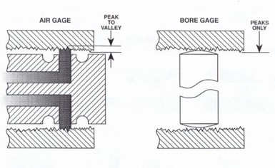
For example, let’s say we have a surface finish of 100 microinches on a part, and we’re measuring with an air gage comparator and two-jet air plug that has a range typically used to measure a 0.003-inch tolerance. The typical gaging rule of thumb says you should have no sources of error greater than 10 percent of the tolerance. In this example, that’s 0.0003 inch. If we used this plug on the 100-microinches surface, the average measuring line would actually be 50 microinches below the peak line. Double this error for the two jets and you get 0.0001 inch, or 30 percent of the allowable error. That’s pretty significant, and air would probably not be a good choice for this part. As a general rule, the limit for surface finish with an air gage is about 60 microinches, but it really depends on the part tolerance.


Related Content

4 Ways to Establish Machine Accuracy
Understanding all the things that contribute to a machine’s full potential accuracy will inform what to prioritize when fine-tuning the machine.
Read More
How to Choose the Right Cut Off When Measuring Roughness
Measurement results for surface finishing parameters can vary depending on the filter parameter (Lc), also known as the cutoff.
Read More
Understanding Errors In Hand-Held Measuring Instruments
Different instruments (and different operators) are prone to different errors.
Read More
A Case for Combining Workholding with Optical Scanning
Automotive dies and die inserts are often complex, one-off parts with little room for error. Integrity Tool's investments in modular workholding tools and 3D optical scanning have allowed the company to create niche capabilities for its CNC machined parts.
Read MoreRead Next

3 Mistakes That Cause CNC Programs to Fail
Despite enhancements to manufacturing technology, there are still issues today that can cause programs to fail. These failures can cause lost time, scrapped parts, damaged machines and even injured operators.
Read More
The Cut Scene: The Finer Details of Large-Format Machining
Small details and features can have an outsized impact on large parts, such as Barbco’s collapsible utility drill head.
Read More
