
Why Are Holes Circular?
Geometries that are easy to machine may not be easy to fabricate additively.


We begin this month’s column with that simple question: Why are holes circular? Is it because creating them that way makes for the most efficient use of material? Is it because that is how nature makes them? I think the answer is because that is how we are used to machining them. Drilling a hole is fastest and easiest when that hole is circular. This mindset is rooted in our conventional way of thinking about manufacturing—as a subtractive process that removes material from an existing block or piece of stock.
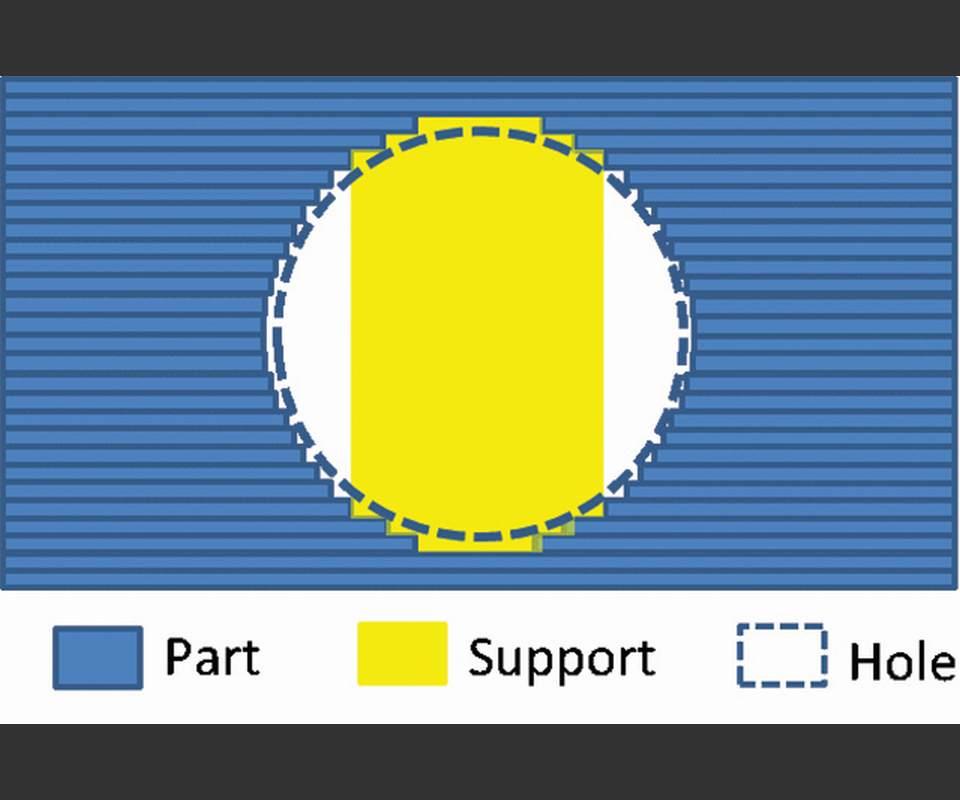
In additive manufacturing, making a circular hole actually can be quite difficult, depending on its size and orientation. This may be hard to believe, but it is true, especially when the hole runs perpendicular to the direction of the additive build, as shown in the first image in the above slideshow. Because in the additive process the part is built up layer by layer (shown in blue), the resulting geometry will show a “stair step” around the perimeter of the hole, and support structures (shown in yellow) will likely need to be created in order to support the overhang as the top of the circle is approached. Granted, this image over-emphasizes the thickness of the layers, but even at 20-60 microns (typical layer heights for current laser-based powder bed fusion systems), circular holes oriented perpendicular to the build direction are far from perfectly circular. Even holes that run parallel to the build direction can encounter issues of distortion and surface finish—but that is a discussion for another day.
So I ask again: Why are holes circular? In additive manufacturing, they do not necessarily need to be. In fact, they are easier to print when they are not circular. By easier, I mean that we do not have to add in support structures, which then need to be removed after fabrication. This is what made the automotive component in last month’s column so difficult and challenging to build. Namely, it required lots of circular holes and interfaces in order to connect the part to the wheel fasten to the suspension of the racecar. In that case, the holes had to be circular because of the mating interfaces. Eventually, though, additive manufacturing will help us reduce the number of mating interfaces needed, because we can design and fabricate multi-piece assembles as a single 3D-printed part (GE’s LEAP nozzle is the leading example of this right now).
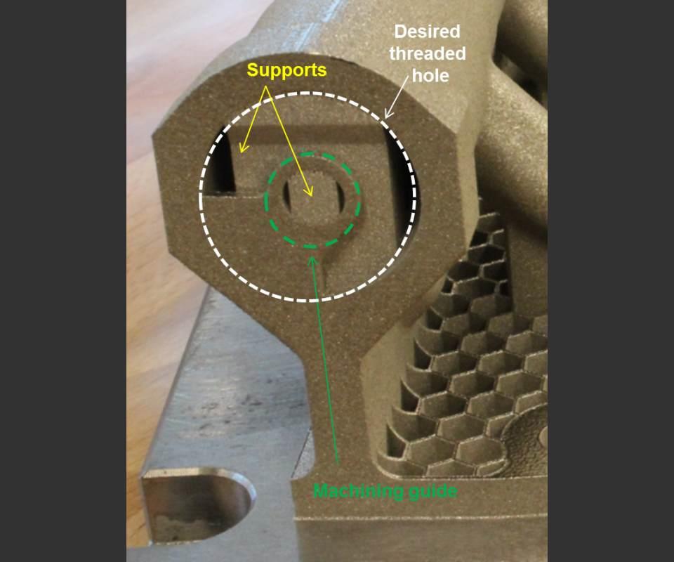
For now, if you want to build a horizontal hole that mates to a circular part using AM, try using the support structures to your advantage. The second image above shows a great example of a design one of our design engineers and AM experts, Corey Dickman, came up with for a threaded interface.
The hole was large enough that it needed support structures inside, and the threads were small enough that they could not be printed. Corey quickly realized that the printed hole would need to be machined and tapped afterward to mate with the connector, so he designed a machining guide inside the support structure that would help align the part and tool for this machining. This design enhancement required minimal extra build time and material, yet it saved a fair bit of post-processing time while also giving the tool enough material to “bite” into when machining. Support structures are not usually fully dense and can cause problems during machining, however, and we will discuss this issue in a future column. In the meantime, think about why the holes you create are circular and whether they really need to be—or if that is just the easiest way to make them.


Related Content

How To Calibrate Your Calipers
If you’re interested in calibrating your own digital, dial or Vernier calipers, here are some steps to take to make sure it goes off without a hitch.
Read More
Understanding G27, G28, G29 and G30
Take a closer look at these reference position commands.
Read More
How to Reduce Cycle Times by 70% and More on Your Existing CNCs and Dramatically Improve Tool Life Too
By employing advanced high efficiency milling techniques for the entire machining routine, SolidCAM’s iMachining technology can drastically reduce cycle times while vastly improving tool life compared to traditional milling.
Read More
Understanding The Four Major Behavioral Styles
Companies today are expanding the role of teams in the workplace in an effort to empower employees and improve organizational effectiveness. The more we try to work as a team, the more important it becomes to recognize that people exhibit different behavioral styles.
Read MoreRead Next

The Cut Scene: The Finer Details of Large-Format Machining
Small details and features can have an outsized impact on large parts, such as Barbco’s collapsible utility drill head.
Read More

3 Mistakes That Cause CNC Programs to Fail
Despite enhancements to manufacturing technology, there are still issues today that can cause programs to fail. These failures can cause lost time, scrapped parts, damaged machines and even injured operators.
Read More