
A New Milling 101: Selecting Tool Materials and Coatings
Part 4. The emergence of new workpiece materials is driving the development of new cutting tool materials and tool coatings. These, in turn, are driving the development of new milling processes and techniques.
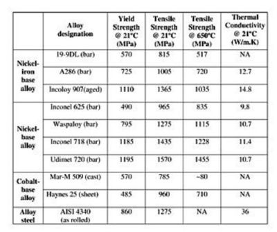
Fig.1--Properties that allow parts made from alloyed materials to perform better in their intended application also present special challenges for milling tools.
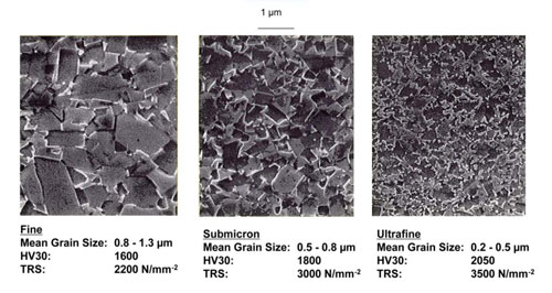
Fig. 2--As shown in this comparison of WC-6Co carbide materials with varying grain sizes, Vickers microhardness and transverse rupture strength (TRS) both increase with decreasing grain size.
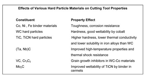
Fig. 3--Using different hard particles and binder materials allows cutting-tool manufacturers to engineer application-specific tool materials.
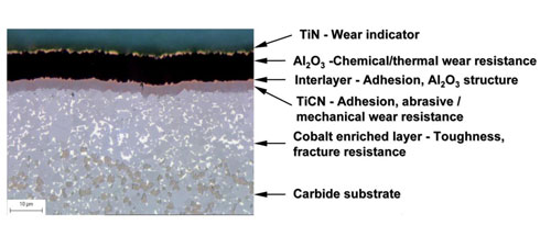
Fig. 4--Multi-layer coating system for milling inserts consists of (from top): thin TiN wear indicator layer; Al2O3 layer for chemical and thermal resistance; thin, adhesion-promoting interlayer; and TiCN layer for wear resistance.
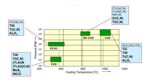
Fig. 5--Comparison of coating processes shows coating temperatures and pressures as well as the materials typically deposited in each process.


This installment will outline the current state of tool material and coating technologies and discuss the factors driving new milling grades.
- High hot hardness, i.e., retention of the cutting edge at elevated temperatures near the tool/workpiece interface.
- Ability to withstand high cutting forces during machining.
- Low thermal conductivity to resist edge degradation such as depth-of-cut notching, plastic deformation, and oxidation caused by high temperatures at the cutting edge.
- Chemical inertness to minimize formation of built-up edge (BUE) and the possibility of coating delamination.
- High wear resistance to reduce abrasive wear at the cutting edge due to hard intermetallic compounds in the microstructure.
- Geometry that provides efficient cutting, good chip-breaking, and minimizes heat generation during machining to reduce subsurface defects on the workpiece.
See Figure 1.
Concurrent with the development of new, difficult-to-machine work materials is the desire of machine shops to improve productivity, profit margins, workpiece quality, and shorter lead times. The need for continuous improvement of milling operations has resulted in multiple new production technologies, such as trochoidal milling, dry machining, hard milling, and high-speed cutting (HSC).
The substrate material of any milling tool must provide good resistance to plastic deformation and thermal and mechanical shock. For milling, shops can choose from tungsten carbide, cermet, ceramic, and superhard tool materials. Each material type is highly engineered to deliver the properties required for a given application.
|
Figure 3--Effects of Various Hard Particle Materials on Cutting Tool Properties Constituent Property Effect
Co, Ni , Fe binder materials Toughness, corrosion resistance
WC hard particles Hardness, good wettability by cobalt
TiC, TiCN hard particles Higher hardness, lower thermal conductivity
and lower solubility in iron alloys than WC
(Ta, Nb)C Improved high-temperature properties and thermal shock resistance
VC, Cr3C2 Grain growth inhibitors in WC-Co materials
Mo2C Improved wettability of TiCN by binder in cermets
|
Cermets are produced using essentially the same techniques as cemented carbides, but use alternative binder and hard particle materials. Binder materials may be a mix of cobalt, nickel, and iron, and hard materials may include titanium carbide (TiC), titanium carbonitride (TiCN), and carbides of tantalum, vanadium, chromium, or niobium.
Sialons have a low coefficient of thermal expansion and high thermal conductivity, which provide very good resistance to thermal shock and thermal fatigue. They are well-suited for milling of superalloy workpieces.
Superhard Materials. At the pinnacle of milling tool materials in terms of hardness and wear resistance are superhard grades, including multiple forms of diamond and cubic boron nitride (CBN). Diamond-based materials include polycrystalline diamond (PCD) and diamond coatings deposited by a variety of methods.
Deposition Rate, µm/hr 0.5-1 1-1.5


Related Content

All-Around Mill Improves Productivity and Cost for Valve Job
Adopting a mill with a double-negative rake and pockets compatible with multiple insert geometries enabled Progressive Metal Service to increase feed and lower scrap rates for a valve.
Read More
How to Turn Machine Shop Downtime Into Process Expertise
To take advantage of a lull in business, JR Machine devised a week-long cutting tool event that elevated the shop’s capabilities with aerospace alloys.
Read More
Threading On A Lathe
The right choices in tooling and technique can optimize the thread turning process.
Read More
Choosing Your Carbide Grade: A Guide
Without an international standard for designating carbide grades or application ranges, users must rely on relative judgments and background knowledge for success.
Read MoreRead Next

A New Milling 101: Cutter Design and Application Considerations
Part 2: Cutting tool geometry governs almost all design and application considerations related to various milling choices.
Read More
A New Milling 101: Milling Forces and Formulas
The forces involved in the milling process can be quantified, thus allowing mathematical tools to predict and control these forces. Formulas for calculating these forces accurately make it possible to optimize the quality of milling operations.
Read More
A New Milling 101: What Customers Demand
Part 5. For W Machine Works in San Fernando, a custom variation of the WIDIA-Hanita VariMILL II solid end mill proved especially effective in roughing and semi-finishing applications in stainless steels, high-temp alloys, nickel- and carbon-based alloys, and titanium.
Read More