
Affordable Technologies For Aerostructure Machining
A research project tests the extent to which non-traditional choices related to tooling and technique can make a machining center more capable for milling complex parts.


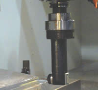
This compact right-angle head is driven by the machining center’s coolant system.
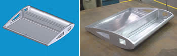
The proof-of-concept part was designed to include features typical of complex modern aircraft structures.

Optimal machining parameters were found for various machine-and-tool combinations. Stability maps such as the one shown indicate chatter-free combinations of spindle speed and depth of cut.
Replacing an assembly with a single machined piece in the production of complex aircraft structures can reduce the total number of build hours, decrease weight and increase strength. Aurora Flight Sciences (Bridgeport, West Virginia), along with NCDMM, the National Center for Defense Manufacturing and Machining (Latrobe, Pennsylvania), recently worked on a project aimed at reducing the cost of making these complex integral structures. The goal of this project was to bring together several relatively low-cost machining technologies in the production of a 6061-T651 aluminum proof-of-concept piece. Those technologies included plunge rough cutting, heat shrink tool couplings, a fluid-driven right angle head attachment and frequency response measurement of machine-and-tool combinations to find their optimal machining parameters.
The proof-of-concept piece included features typically found in complex modern aircraft structures—features such as pocketing, windows, “C” and “I” type structures, and thin walls and skins. (See illustration below.) The machining operations included roughing, slot milling, finish profiling and pocketing. Machining was performed in three setups, with the right angle head improving the machine’s access in some cases by allowing the machine to reach side features of the part. Developing and refining this machining process led to a variety of useful conclusions, any one of which might be relevant to many other complex parts. The points that follow summarize a portion of the research findings.


1. Plunge roughing is more effective in harder material. During programming for the proof-of-concept piece, it was determined that plunge rough cutting would not result in the highest material removal rates. Milling was more productive with the feed rates and depths of cut possible with large-diameter face mills.
To extend the investigation, however, plunge rough cutting was applied to a representative titanium aircraft fitting to determine its effectiveness in a harder-to-machine metal. Here, plunge rough cutting reduced the machining time by 21 percent. While specific savings may depend on the part design, it is fair to generalize that plunge rough cutting makes more sense in harder-to-machine materials in which the effectiveness of traditional milling tools and methods is much more constrained.
2. Shrink fit improves holding torque and runout. Tests by NCDMM demonstrated that the gripping torque of heat-shrink toolholders is dramatically higher than that of more standard toolholders for larger tool shank diameters (that is, diameters on the order of 3/4 inch and up). The heat-shrink tooling system that was chosen for this project uses a series of coils to rapidly heat the toolholder so it expands. The expansion allows the tool to be inserted, then the holder is rapidly cooled using forced air or coolant immersion. Another advantage of holding the tool in this way is that tool runout is reduced by up to 60 percent.
Shrink fit is another technology that may be even better suited to the harder-to-machine metals. With the increased gripping torque, a larger tool diameter and stepover may be used in hard materials to achieve an increased material removal rate. (In our own aluminum work, the large diameter and stepover were already possible.)
3. A fluid-driven right-angle head can be an effective option for tight spaces. The right angle head chosen for machining side features was supplied by Eltool (Cincinnati, Ohio). Instead of being gear-driven, this fluid-driven head uses the machining center’s through-spindle coolant system to drive the cutting tool via a positive-displacement ball piston motor. This mechanism allows the head to be small, and some related models from this company are able to fit within a 1-inch bore.
The speed and torque of the head are directly proportional to the through-spindle coolant flow rate and pressure. In the proof-of-concept application, the coolant delivery of the machining center allowed the head to deliver 950 rpm with a torque of 5.7 inch-pounds at 0.082 hp. These were sufficient parameters for machining the 6061 aluminum.
4. The process can improve in unexpected ways through changes to the tool length or toolholder. The tools and their respective toolholders were all dynamically tuned within the spindle of the Haas VR-11 five-axis machining center used during this project. This process—involving an accelerometer attached to the end of the tool and a hammer containing a piezoelectric transducer—aims to find the optimum spindle speed and depth of cut for a particular combination of machine and tool. When the machine/tool combination is excited with the piezoelectric hammer, the frequency response and compliance of the system allow a stability map to be generated. This stability map shows the stable depth of cut as a function of spindle speed at a specific tool stepover. Along a typical map are one or more speeds where the cut can go particularly deep without chatter. These optimum speeds are what machinists typically refer to as the “sweet spots.”
Tool length affects the stability map. In one case, a 1-inch end mill was tested in the same toolholder at reaches of 3.75 inch and 3.50 inch. The testing was performed with a constant tool stepover of 0.75 inch and spindle speeds no greater than 7,500 rpm. Within these parameters, however, the allowable depth of cut increased from 0.025 to 0.05 inch as a result of this change in length.
The toolholder can also affect the stability map. In place of the toolholder used above, a traditional side-lock toolholder was used. At a tool reach of 3.75 inch, a maximum depth of cut was found at a spindle speed of 6,500 rpm. The stability map for this tool and holder combination is shown. (See illustration on the next page.) The red areas indicate the predicted regions where chatter would occur.
5. Predictive testing of stable spindle speeds provides a reliable starting point. The stable cutting at theoretically predicted spindle speeds was verified in test cuts. However, various other sets of cutting parameters were also tested experimentally, in order to determine what parameters the operator would choose for the selected tools without the dynamic tuning. During these trials, the experienced operator was able to find effective sets of parameters that were similar to those suggested by the theoretical stability maps, but with a few notable exceptions. Overall, the results of independent attempts to find optimum parameters suggested that the dynamic tuning provides an excellent starting point when machining expensive materials or evaluating a new tool or holder combination. Test cutting to search for optimum parameters may still be needed to improve the metal removal rate further, but the dynamic tuning starting point can reduce the amount of this test cutting that is needed.
Results
The proof-of-concept piece was completed in approximately 33 hours of machining time and 6.5 hours of setup time. Finishing the inside of the airfoil and machining the rib and spar pockets accounted for 22 hours of this time. A total of 1.26 cubic feet was removed from the piece, with the largest amount removed during roughing of the airfoil in the first operation. The airfoil skin thickness, designed at 0.050 inch, had a final tolerance of ±0.002 inch.
The proof of concept piece was compared to an existing structure manufactured at Aurora Flight Sciences without the benefit of the technologies used in this process. A comparison of the manufacturing hours between these two structures indicated that a 40 percent reduction is possible. In addition, the technologies used to make the proof-of-concept piece (particularly the compact right-angle head) might enable part designs that would not ordinarily be considered cost-effective and practical using standard production methods.


Read Next


3 Mistakes That Cause CNC Programs to Fail
Despite enhancements to manufacturing technology, there are still issues today that can cause programs to fail. These failures can cause lost time, scrapped parts, damaged machines and even injured operators.
Read More
The Cut Scene: The Finer Details of Large-Format Machining
Small details and features can have an outsized impact on large parts, such as Barbco’s collapsible utility drill head.
Read More