
Avoiding Costs while Adding Value with DFAM
Design for Additive Manufacturing (DFAM) is as much about finding value as it is about avoiding costs with AM.


As much as people like to hype the “free complexity” of additive manufacturing (AM), we all know how expensive the reality can be. Last month, I focused on how Design for AM (DFAM) can be used to add value to an AM part by taking advantage of the “free complexity” that comes with layer-wide fabrication methods enabled by the different AM technologies. This month, I want to focus on the flip side of that coin, namely, how DFAM enables cost avoidance, adding even more value to AM parts. The combination of cost-avoidance and value-creation give DFAM a powerful one-two punch when it comes to the adoption and industrialization of AM.
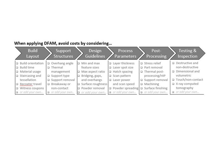
Careful consideration of each of these factors when applying DFAM will help you avoid unnecessary costs when using AM.
The myriad of factors and steps that can add cost to an AM part, particularly a metal part made with laser powder bed fusion (PBF), tend to fall into six broad categories, much like the value drivers discussed last month. First, and foremost, is build layout (see figure). Designers need to be mindful — or at least cognizant of — the build orientation when applying DFAM as this has cascading ramifications on build time, material utilization, support structures, and a whole host of factors that drive up costs. For instance, staircasing and tessellation effects (if using STL files) can cause headaches during build layout, leading to additional post-processing and finish machining if not taking into consideration early. The direction of recoater travel is also important to consider when planning a build. While a designer may not get into this level of detail with build layout, it is worth understanding the impact — figuratively and literally — that the recoat travel may have on small or delicate features during the build. Finally, the designer may wish to consider adding witness or test coupons or powder coffins to the build plate as space permits. This could save lots of time, energy, and cost later should anything go wrong.


While not all AM processes require support structures, they can be a significant cost driver when making metal AM parts with laser PBF: they add build time and cost, consume material, and must be removed afterward, creating unwanted and unnecessary scrap. Supports are needed for features that exceed a critical overhang angle, as they help manage the thermal cycling and mitigate the residual stresses that build up in a part as it is being fabricated. There are multiple types of supports that can be used, and custom-designed supports may be best for complex geometries. Supports may be hollow or solid, which have implications on build time, material usage, and powder entrapment, and support removal also needs to considered during DFAM. For example, having a support inside a complex internal passageway may be impossible to access and remove, restricting flow or causing blockages that may lead to failure. Breakaway supports can be designed to be easily removed, and in some cases, non-contact supports may suffice to help dissipate heat and mitigate distortion without contacting the actual part. The designer should specify — or at least work very closely with a process engineer — to think through support design to avoid excessive material, build, and post-processing costs that they add.
Next comes design guidelines for a specific AM machine and, more generally, for each AM process. These help reduce the likelihood of build failures, which drive costs up, and ensure that dimensional integrity and performance of the AM part is within specification. Each machine and material will have an associated minimum (or maximum) feature size, aspect ratio, bridging and overhang lengths, to name a few, and these will be correlated to the specified build orientation. Build orientation also drives surface roughness, which may lead to additional post-processing and surface finishing in many cases. Again, this adds cost and should be considered during DFAM. Powder removal can also be a big issue with laser PBF, especially powder that is trapped inside hollow features, sophisticated internal passageways, or small lattice structures, for instance. The longer it takes to get all of the powder out of the part (and off the build plate and from within the supports), the more it costs—and the more material you waste (as you may not be able to reuse and recycle this trapped powder).
Similar to the design guidelines, the process parameters and process settings are specific to each machine and each material. While many of these will be fixed, or optimized for each machine and material by a process engineer, designers need to be cognizant of the potential impact of influential process parameters on the ability to print and resolve the geometries being designed. For instance, layer thickness will impact staircasing and surface roughness while laser spot size, hatch spacing, and scan pattern while influence the ability to resolve and print the thin walls you might find in an AM heat exchanger, for example. Laser power and scan speed may not be under the direct influence of designers, but they are certainly important things to be aware of as they drive productivity but can lead to defects and build failures, which add cost. In short, designers should work very closely with their process engineers to understand how key process parameters will influence the likelihood of build failure while striving for build success the first time.
Post-processing is another area that drives up the cost of a metal AM part, and it may very well be the best place to save time and money when it comes to DFAM. Stress relief, part removal, thermal post-processing and/or HIP (hot isostatic pressing), support removal, machining, and surface finishing can all be expedite based on judicious design decisions. For instance, if you cannot eliminate support structures entirely, then strive to make them integral to the structure so that they do not need to be removed, saving costs during this step. Likewise, you can design references or features into the part to establish datums or help align/fixture parts for machining. You could also offset the part from the build plate a bit more to use a band saw versus wire EDM (electrical discharge machining) to save time (and hence cost) to remove the part from the build plate. I have also seen parts designed such that the thermal post-processing occurs during its operation, eliminating this post-processing step entirely. Creative uses of DFAM to avoid costs during post-processing will keep from doubling (or worse) the cost of your metal AM.
Finally, testing and inspection costs can also be reduced with DFAM. Witness and test coupons added to the build can provide additional assurances about the microstructure and mechanical properties with little added cost. Meanwhile, designing “intelligent test coupons” that help validate one or more functions or features of the AM part with smaller-scale testing helps reduce uncertainty and de-risk the process with less cost. Designers should also consider how the part is going to be inspected, dimensionally and volumetrically, using contact or non-contact methods (e.g., ultrasound, digital radiography, dye penetrant, etc.) or more expensive x-ray computed tomography. Spending a little time thinking about testing and inspection goes a low way in saving cost (and time) necessary for AM part qualification and certification.
All told, DFAM can drive value and avoid costs in every step of the AM workflow, but only if you are cognizant of the entire process chain. So, how knowledgeable are you?


Related Content

Go Digital: How to Succeed in the Fourth Industrial Revolution With Additive Manufacturing
The digitalization of manufacturing is set to transform production and global supply chains as we know them, and additive manufacturing has been leading the way in many industries.
Read More
The Benefits of Vertically Integrating Metal 3D Printing and Machining
Having 3D printing and machining within one organization enables Addman’s engineers to collaborate and consolidate so it can quickly make successful metal 3D printed parts.
Read More
Digital Thread Enables First-Time-Right 3D Printing
Connecting all stages of manufacturing, from design to postprocessing, helps break down barriers to industrializing additive manufacturing.
Read More
10 Ways Additive Manufacturing and Machining Go Together and Affect One Another
Forget “additive versus subtractive.” Machining and metal additive manufacturing are interconnected, and enhance the possibilities for one another. Here is a look at just some of the ways additive and machining interrelate right now.
Read MoreRead Next

How a Worksheet Can Elevate AM Success
How a simple worksheet can help improve success with additive manufacturing.
Read More
AM Brings Down the Wall Between Manufacturing and Design
In additive manufacturing, design and manufacturing blend together. They can’t be separate if AM is to realize its promise.
Read More
Gantri’s 3D Printed Luxury Lighting Brings Designers Closer to Consumers
The San Francisco startup is changing designer lighting with a designer-forward online marketplace and just-in-time delivery enabled by 3D printing.
Read More