
Better Math Makes Scanning Stronger
Evaluating the suitability of a CMM for an application traditionally revolves around determining measurement uncertainty relative to the workpiece size and required tolerances. Generally the CMM should be 10 times more accurate than the tolerance it will verify. But what is the best method of acquiring the data?


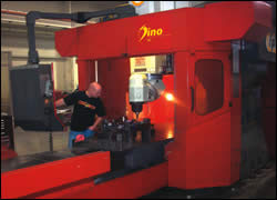

Fig. 1—Continuous probing allows capture of many data points for a test feature in a short time. In numerous test a link has been established between the uncertainty for a test feature and the number of points measured.
Shops using coordinate measuring machines have two general data acquisition methods to choose from. By far the most common probe is the touch trigger (TTP). It has been a CMM staple for many years.
Recently though, scanning probes have been making headway in part because the technology has developed to a point where the scanning machine can be used outside a clean room environment. While the battle to define how much data density is necessary to make a good measurement continues to be fought, current scanning technology, and the better mathematical algorithms that it allows, is gaining acceptance.


CMM specifications for measurement uncertainty are made relative to known or traceable artifacts, such as gage blocks and ring gages. Because these artifacts are used to measure CMM performance, they must be more accurate than the CMM, in most cases as much as 10 times more accurate. As a result, they have near perfect form, which is easily measured.
Accurately evaluating imperfect form, which is the world of production parts, becomes much more demanding because the assumptions about regular form that can be made with gage blocks and ring gages don't apply to vagaries of manufactured parts. This is particularly true with parts becoming more complex and accuracy demands constantly rising.
The science of metrology offers an answer, but it requires trading "good enough" practices for hardware and software solutions that are known to be better. The existing metrology answer—and the future of measurement—is higher data density (Figure 1).
An example of increased data density is the ability to acquire 800 sampling points instead of only eight. The tools that deliver this ability are high-speed scanning and superior, more robust mathematics.
Previously, scanning probes were available only on laboratory or premium-category CMMs. These systems required large capital investments. In addition, restrictive environmental parameters and slow cycle times diluted their value-added to the shop's desire for smooth throughput of its manufactured parts.
Today's scanning probes, by comparison, read hundreds of points in the time that it takes touch trigger probe CMMs to probe just four to eight points.
When measuring the entire diameter of a 143.8 mm bore, for example, a high-speed scanning CMM can take 831 measuring points in 11 seconds. The 30-second scan of a 52.8 mm bore milled on a CNC machining center yields approximately 3,000 measuring points. And it can all be done on the shop floor.
Function Follows Form
When measuring a near perfect artifact, probe point quantities and locations are insignificant in calculating the result. In measuring production parts, however, CMMs inspect imperfectly formed features and then mathematically relate sampled points to geometric elements such as circles, planes and cylinders.
The result can vary according to where the CMM samples each feature. This means the quality of size, location and form information is directly related to the number of samples and the location of each point.
Most people understand the need for high data density when evaluating form. It is not as well known that form must also be understood in order to provide truly accurate location and size evaluation. If you don't know true form, you can't know the functional size and location.
Form deviation is present in all features. It's the magnitude of the deviation that varies. An example using a two-lobed diameter shows that functional size can be affected by as much as one-half the form deviation when using only four sample points.
Measuring a common three-lobed diameter with only four points shows an error in size that is approximately 70 percent of the form deviation. The error in location is approximately 60 percent of the form deviation.
These errors are significant when compared to the 10-to-1 rule for desired gage accuracy. Even in these simple, common applications, the error directly attributable to low data density can be as great, or greater than, any error inherent in the CMM. That's why it requires a minimum of 300 points to evaluate a form like the circularity of a diameter in the 25 to 70 mm (1 to 3 inch) range. This level of data density is the minimum necessary to determine 90 percent or more of the correct form value.
Power In The Math
A study done by Zeiss compared results from an existing TTP program to results using a scanning probe. The company's scanning methods also employed alternate algorithms, not the commonly used Least Squares (Gauss) mathematics. The TTP and scanning methods were both applied to a cast iron pump housing. Both methods were executed using the same CMM.
For 18 of the 45 characteristics included in the study, results from the two methods differed by more than 10 percent of the tolerance range. In eight of those instances, scanning-enabled high data density inspection identified out-of-tolerance characteristics which "passed" under the TTP method.
The potential error from low data density is even larger given that most measurements are not simple, 2D entities. In many applications, 3D form variations of workpieces must also be considered.
The limitations of low data density and Least Squares mathematics came to light a decade ago when a GIDEP (Government Industry Data Exchange Program) alert addressed potential problems in inspection methods that stray from the functional intent of an engineering drawing. The alert confirmed that Least Squares math is not the most correct way to evaluate flatness, straightness, parallelism and perpendicularity.
The problem, however, extends beyond those four characteristics. Least Squares does not provide a functional size or location. And it does not evaluate form properly. The ultimate requirement—the contemporary solution—is better mathematics.
If Least Squares is not the optimum mathematical algorithms, why is it used? The answer is that the algorithms, which provide "more correct" data evaluation, require very high data density to produce stable and reliable results.
Other methods—maximum inscribed elements, minimum circumscribed elements, and minimum zone elements—each have a specific purpose (Figure 2). And given enough data, they produce considerably improved functional results. Least Squares is simply the best available solution for producing repeatable results when dealing with low data density.
High Density And Improved Process Control
In their role as process control gages, CMMs are evaluated with Gage Repeatability and Reproducibility (GR&R) tests. A GR&R can be a more difficult test of accuracy than simply identifying a machine's measurement uncertainty. This is because GR&R tests are conducted on production parts instead of traceable artifacts. The test parts have form errors, which affect the ability of a sampling device to generate the same answer when multiple parts are measured multiple times by several operators (Figure 3).
Once again, high data density is the solution. Sampling several hundred points significantly improves GR&R results by eliminating dependency on where the data is taken from one trial to the next.
In a GR&R test that compared a high data density scanning CMM to a lower density gathering CMM using a TTP, Zeiss measured an aluminum electric motor housing. The test checked 29 characteristics in a two-operator, three-trial study.
The high data density solution repeated approximately twice as well as the low data density method. Reproducibility was approximately ten times better. The highest improvement in a measured characteristic was 75 percent for a projected true position. High data density improved the results for five other characteristics by 20 percent or more. Overall, the improvement averaged 11 percent.
An increasing number of companies are seeing the advantages higher data density can bring to improving products and processes. Using high data density to generate better functional evaluations of size and location enhances outcomes from identifying assembly problems, to reducing warranty cost exposure. The key is to understand that the influence of form on size and location can be greater than any error inherent in a CMM.
Adding this consideration to the 10-to-1 gage tolerance rule improves the ability to select an inspection engine (high data density) and a methodology (high-speed scanning) that provide the best chance to stay within the tolerance range—repeatedly—on imperfectly formed production parts.
About the author: Rich Knebel is an applications engineer for Carl Zeiss IMT Corporation (Minneapolis, Minnesota).


Related Content

Understanding Errors In Hand-Held Measuring Instruments
Different instruments (and different operators) are prone to different errors.
Read More
Choosing the Correct Gage Type for Groove Inspection
Grooves play a critical functional role for seal rings and retainer rings, so good gaging practices are a must.
Read More
Determining Out-of-Roundness at the Point of Manufacture
George Schuetz, Mahr Inc.’s Director of Precision Gages, offers these techniques for measuring roundness on the shop floor.
Read More
4 Ways to Establish Machine Accuracy
Understanding all the things that contribute to a machine’s full potential accuracy will inform what to prioritize when fine-tuning the machine.
Read MoreRead Next

Scanning For Process Improvements
A coordinate measuring machine with a constant-contact scanning probe makes it possible to get better, more complete information about workpiece features, especially contours. Two shops talk about how this information helps streamline their production processes.
Read More
3 Mistakes That Cause CNC Programs to Fail
Despite enhancements to manufacturing technology, there are still issues today that can cause programs to fail. These failures can cause lost time, scrapped parts, damaged machines and even injured operators.
Read More
