Boost Metal Removal Rates with Constant Chip-Load Machining
Sponsored ContentThe benefits of constant chip-load machining have been known for a while, but efficiently programming the toolpaths was impractical for most shops. However, new CAM technology makes the process easy, and the improvements in machining productivity can be dramatic.


No doubt there is more productive CNC machining technology coming to market every day. But how can you get more productivity with the machining centers and turning centers you already own?
By updating your machining strategies.
It starts with the cutting tool. The key to more productive machining is using milling and turning tools in the way they were intended, at optimum feeds and speeds and, most importantly, optimum chip loads. Do that and you can dramatically improve metal removal rates, surface finishes and tool life.
For most shops, the barrier to achieving these gains is not their equipment but their ability to generate part programs that consistently keep tools in the cut under optimal conditions. Well-known CAM developer, Mastercam, has an answer for that with its Dynamic Motion toolpath engine. This CNC programming technology dynamically generates the most efficient toolpaths that maintain a constant chip load in the sweet spot of any cutting tool’s true cutting capabilities. Much more efficient machining is the result, with metal removal rates as much as 70% higher than conventional machining.
The Problem with Traditional Toolpaths
Tools are designed to cut, or more accurately, shear material. The tool design is intended to cut the material with a target chip load, which sends as much of the generated heat as possible into the chip and evacuates that chip away from the workpiece. How well the combination of spindle speed, feed rate and toolpath motion is able to maintain the tool’s target chip load determines how well that tool will perform and what type of tool life you will achieve.
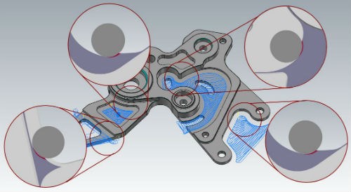
Conventional toolpaths are often generated by applying an offset to the part geometry. This leads to moments where the tool is buried in the material.
The problem with traditional part programing is that it is driven, first, by the geometry of the part. A common result is that tools get over engaged particularly in tight corners or during sharp directional changes. To compensate, the programmer typically adjusts feeds and speeds for the worst-case scenario—usually a corner where the tool is buried into material—and applies those parameters to the entire cut.
That results in the tool operating outside the optimal chip load for most of the cut. Either the tool gets over-engaged in corners or gets substantially underutilized for the rest of the path, and sometimes both. Cycle times grow unnecessarily long, and tool life gets shorter.
Keeping Chip Load Constant
An alternative cutting strategy is based on radial chip thinning (RCT), known more broadly as constant chip load machining or high-efficiency machining, which improves machining efficiency and tool life. For conventional machining, tool manufacturers typically recommend cutting parameters assuming a stepover of 50% of the tool diameter. Feeds and speeds are adjusted accordingly to deliver an ideal chip load. With radial chip thinning, the stepover is reduced, which of course also reduces the thickness of the chip under the same feed rate. To compensate, the feed rate must be increased accordingly to yield the desired chip thickness.
Radial Chip Thinning (right) vs. a Conventional Cut
The other big difference with this cutting strategy is in the depth of cut. A traditional approach is to step down 25% of tool diameter. With RCT, the depth of cut can be as much as two to three times tool diameter, depending on the tool. With the deeper depth of cut, you get much better utilization of the tool’s entire cutting edge, rather than just always cutting with the end of the tool. And since the side load on the tool is greatly reduced (from 50% stepover to around 15% or less) there is also less load on the spindle, which will save wear and tear on your machines. You may even be able to cut some jobs on lighter duty equipment.
Best of all, this combination of faster feeds, speeds and deeper cuts can typically improve metal removal rates by 60 to 70 percent or more compared to conventional machining practice.
Dynamic Motion Keeps Cutting at Optimal Rates
But there’s a catch. The benefits of RCT described so far can only easily be achieved with straight-line cuts. So, what do you do with pockets and other forms of profile geometry?
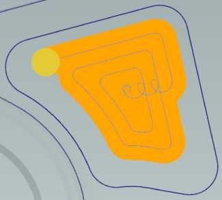
This is where dynamic motion comes into play. It dynamically adjusts the motion or trajectory of the toolpath such that the tool remains safe and the chip load is consistent, even during directional changes. Unlike traditional a toolpath that is primarily generated by offsetting the geometry it was based on, dynamic motion maintains the same chip thickness regardless of where the tool is or the material it is cutting.
With dynamic motion, constant chip load is maintained even when
navigating through directional changes.
Dynamic motion takes the optimum “straight-line” feed rate improvement of radial chip thinning and enables you to apply it to any pocket or contour, whether it be an open pocket, closed pocket, loose or tight geometric condition. The advantage is that once you are satisfied with your feed rate parameters for a given material, tool and tool diameter, you can feel confident that the toolpath generator always keeps your tool in a safe, optimum cutting condition regardless of part geometry.
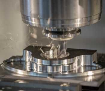
While dynamic motion can’t change the cutting capabilities of your machine tools, it will enable you to get much more out of that equipment. For example, look at the cuts taken on this Okuma machining center, and see what an RCT cutting strategy looks like in action.
Here, 1045 steel is being cut on an Okuma M560 vertical machining center at 550 ipm
and 11,300 rpm. The stock size is 5.25" × 5.25" × 2.75".
Power Cutting
An application of dynamic motion that will require a heartier machine and cutting tools is called “Power Cutting.” While still taking advantage of constant chip load machining, power cutting uses very aggressive stepovers and deep depths of cut, but with traditional feeds and speeds. It can only be used with cutting tools (typically solid carbide) designed for full slotting applications.
Regardless, when the tool is right and on a high power and torque machining center, power cutting can deliver metal removal rates even greater than radial chip thinning. Since aggressive stepovers are being used, tool life will decrease, though early tests are only showing a reduction of 10-15%. Nonetheless, consistent chip control means you will get the highest level of tool life possible under these cutting conditions.
Radial Chip Thinning vs. Power Cutting
This video shows a comparison of RCT and power cutting, both using dynamic motion to maintain a constant chip load. The first high-speed toolpath uses a high end 3/8th inch end mill with a small stepover, 2X diameter deep and running at a fast feed rate. The metal removal rate is very good, about 9.3 cubic inches per minute.
In the second power cut, the same tool is used with a 75-80% stepover and a much slower feed rate, but the same depth of cut. With this cutting strategy, the overall cycle time is reduced by a third.
For Turning Too
The same principles of RCT milling can also be applied to some turning operations and can dramatically increase roughing efficiency and tool life. Called “Dynamic Turning”, this cutting strategy is designed for ceramic and button inserts aimed at turning difficult-to-machine materials.
Dynamic turning uses the same principles and similar toolpath strategies as milling.
Traditional roughing cycles typically use linear motion with sharp directional changes. This concentrates material contact on the tip of the tool and produces over-engagement, a repeated wear pattern, and notching at the same area of the insert with each pass. The cumulative wear pattern coupled with sharp directional changes can seriously damage the cutting edge, limit a tool’s shearing ability and shorten the overall tool life.
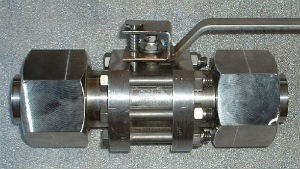
The spool-shaped cylinder for this valve is made of Hastelloy C276. It originally took 5 hours to turn the 220-mm stock down to 120 mm, partially because it required many insert changes for each part. Using dynamic turning with an 8 mm full radius insert, machining time was reduced to 40 minutes with just 1-2 inserts per part.
Dynamic roughing, however, uses proprietary non-linear, non-repeating motion that spreads the wear pattern over a larger area of the insert with each pass. Dynamic motion maintains a consistent chip thickness regardless of the geometry it is cutting. This greatly reduces wear on the insert and can increase tool life by up to 300%. This is especially evident when roughing hard or difficult materials such Inconel and Hastelloy.
Whether milling or turning, constant chip load cutting can produce substantial gains in machining productivity. Ultimately, it removes more material and increases tool life. It’s easier on your machine tools, and it lets you cut more aggressively with lighter machines. And perhaps best of all, it works on any machine.
To talk to a local CAM expert who can show you how Dynamic Motion fits into your shop, click here.
