Compliant Machining Of Composite Wings
Bell Helicopter created a systematic, scripted process to machine composite wing skins and structural components for the V-22 Osprey vertical takeoff aircraft. Custom software ensures there is no deviation from the script.
.jpg;width=70;height=70;mode=crop;format=webp)


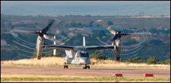
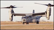
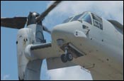
The Bell-Boeing V-22 Osprey is one of the most versatile aircraft ever created. Using tilt-rotor technology, the Osprey combines the lift-off, landing and hovering maneuverability of a helicopter with the speed, range and altitude of a turboprop plane.
Such versatility is also evident in the process by which Bell Helicopter-Textron, Inc., trims, mills and drills that aircraft’s contoured, composite wings and structural components on a single machine tool. This is done using a large gantry machine that has both high-speed milling and waterjet cutting capability, as well as an automated, flexible tooling system to secure both sides of the upper and lower wing skins. Along with such machining versatility, however, comes increased process complexity.


The Osprey’s wing skins are produced and assembled at the Advanced Composites Center located on Bell Helicopter’s campus in Fort Worth, Texas. The precision machining operations are performed after lay-up and curing of a composite wing skin (each skin represents more than $250,000 in manufacturing cost at this stage). Trimming is required for the wing skin’s periphery and multiple stringers attached under the wing skin. Oval holes must be created for access panels. Drilling and countersinking are necessary so rivets can be installed to reinforce the bond between the wing’s skin and stringers.
Consolidating these different operations on one machine platform, which the company calls the Trim Cell, is only part of the challenge. The spring-back nature of the composite material and the lay-up process also contribute to machining difficulties. For example, the location of specific features such as stringers varies ever so slightly from wing to wing. So even though there are common CAM programs for all machining operations, each program must be modified because no two wing skins are identical. To do this, touch-trigger probing of key features is performed prior to machining to establish true feature position. Then, all the base machining programs are automatically modified and re-named per the measurements when the programs are pulled from a remote computer drive.
All the various loading, probing, programming and machining steps must be carried out in precise order to avoid the chance of damaging a wing skin. That process order, or script, was determined by Joe Chin, principal process engineer for the Advanced Composites Center. Error-proofing software, developed by CNC Engineering (Enfield, Connecticut), ensures that the Trim Cell’s operators and equipment follow that script to the letter.
Mr. Chin explained how the equipment, software and operators work in unison to machine composite wing skins during a recent visit to the Advanced Composites Center.
A Tour Of The Trim Cell
The Trim Cell, which went online in 2004, is the result of a 3-year project headed by Mr. Chin. It centers on a gantry machine designed by Flow International (Kent, Washington) that offers both 5-axis high-speed milling and 6-axis waterjet cutting capabilities. Two types of nozzles are used on the waterjet head—a 55,000-psi standard nozzle for wing periphery trimming and a compact, “side-fire” nozzle for stringer trimming.
Because machining is required for both the outer and inner surfaces of each wing skin, the Trim Cell uses a programmable Pogo flexible tooling system supplied by CNA Manufacturing Systems (Woodinville, Washington). This tooling system uses a grid of 77 hydraulically actuated Pogos that are brought to proper height under the 20-meter-long wing skin and attaches to the wing surface via pivoting, vacuum end-effectors. The shape of the wing skins and location of the stringers dictated the number and layout of the individual Pogos. Program macros bring the necessary Pogos to correct height to support the specific wing skin during machining.
The Pogo system takes up a large portion of the gantry machine’s 10- by 50-foot bed. Dedicated fixturing to secure smaller components such as spars and shear ties is also located around the periphery of the table and is accessible to the machine’s head.
The computer that runs the scripted processing software is located at the trim cell’s operator station. That station also includes the gantry machine’s GE Fanuc controller, spindle load monitor and video monitor for live feeds from any of three cameras located in key positions around the machine. Two cameras are positioned at opposite ends of the bed, and another is mounted on the spindle head. Operators can pan and zoom to different areas of the large bed to view milling or waterjet operations at close range.
A Compliant Machining Example
After determining the type of machine and tooling system, Mr. Chin scripted the sequence of steps and specific tasks within those steps to completely machine the wing skins. The script properly ordered events such as operator input, machine input, capture of machine outputs, position analysis, discretionary decision making, supervisory decision variances and operator prompts.
For process enforcement, a computer-based script execution module serves as an electronic poka yoke (error proofing) mechanism to ensure the process is followed step by step. Mr. Chin refers to this as compliant machining.
Here’s how this all comes together for some of the machining processes for a lower wing skin. The wing skin is loaded so that the inner surface is facing upward to allow trimming of the periphery and stringers. In this position, the stringer cross section forms a “T” that is 1.2 inches away the wing’s inner surface. The scripting software first prompts operators to install the side-fire nozzle into the waterjet head. This nozzle redirects the downward the jet of water and abrasive upward. Its compact design allows it to fit between the stringer and inner wing surface to trim the stringers in an upward direction.
Once the operators verify that the nozzle is properly installed, the wing skin can be loaded onto the machine bed. Each wing skin has tabs with tooling balls that install over three pedestals installed on the machine bed. The operators are then prompted to call up the macro to bring the Pogos to proper height. Vacuum is applied to the Pogos sequentially and the wing skin is secured in proper position.
Once operators verify that the wing skin is properly fixtured, an L-shaped probe co-developed by Bell and Renishaw (Hoffman Estates, Illinois) is used to determine the actual centerline position of each stringer. The probe’s shape allows it to access either side of the vertical portion of the stringers. Following that, another probing routine begins to determine the actual Z-axis height of the stringers. The results of these probing routines are used to modify the subsequent machining program for the side-fire waterjet nozzle, and stringers are trimmed to size.
Stringer routing is then performed using the machine’s milling head and diamond cutting tools. A non-contact laser toolsetter from Renishaw is used to avoid damage that might occur with the conventional method of tool touch-off. After stringer machining is complete, a probing routine ensures that the stringers were machined to tolerance.
Operators are next prompted to install the standard waterjet nozzle that will trim the wing skin periphery. The waterjet’s six-axis head is able to maintain a constant fixed focal point despite the different A-, B- and C-axis positions. After trimming, the periphery of the wing skin is then inspected with a probe to determine trimming accuracy.
This completes machining of the inner surface of the wing skin. Next, operators flip the wing skin for machining on the skin’s outer surface. The tooling tasks are similar to the previous setup. The first machining operation is combined drilling and countersinking of holes for rivets used to reinforce the bond between the wing skin and stringers. The depth of the countersink is critical to ensure that the rivet does not protrude above the wing surface, which would create drag. Because the outer contour of a wing skin varies slightly over its length, an adaptive control system is used for countersinking operations.
This adaptive control is carried out using a countersinking cutter that is housed within a spring-loaded sleeve. The sleeve has a sensor that detects sleeve movement as it contacts the wing surface. That establishes the wing surface’s actual Z position to ensure that the countersinking tool is driven to the proper depth.
The final machining operation is routing of oval access holes and machining a rabbit step around the hole to allow installation of the access panel. After the hole is created, eight locations immediately around it are probed to determine the actual Z level of the wing surface. A drilling and routing program is pulled and modified according to probed features so that the rabbit step that accepts the access hole cover is machined to a depth accuracy of ± 0.015. Similarly to the rivets, this ensures that the cover doesn’t protrude above the wing surface.
Database Building
As the script is executed, a database of activities and results is automatically logged. The database includes information such as part serial number, date, time, operator identity and inspection results of each task. This enhances operator accountability and provides an audit trail available for SPC analysis and possibly for FAA compliance requests.


Read Next


The Cut Scene: The Finer Details of Large-Format Machining
Small details and features can have an outsized impact on large parts, such as Barbco’s collapsible utility drill head.
Read More
3 Mistakes That Cause CNC Programs to Fail
Despite enhancements to manufacturing technology, there are still issues today that can cause programs to fail. These failures can cause lost time, scrapped parts, damaged machines and even injured operators.
Read More