
Confirming Dimensional Accuracy of a Precision Ball
A single diameter isn’t the only measurement parameter that can be used to ensure accuracy.


Balls are present in bearings for both rotary and linear-motion applications in machine tools, they act as contacts and pivot points in gaging equipment and tooling, they can act as plungers in hydraulic pumps, and they serve as masters for size and roundness gaging. They are also useful for checking the parallelism of surfaces on gages with flat anvils and sensitive contacts, including many thickness or snap gages. The user takes measurements with the ball at each corner of a square anvil, or at the 3 and 9 o’clock positions and the 6 and 12 o’clock positions of a round anvil. Knowing these readings, the user adjusts the anvil accordingly to bring all points within the parallelism tolerance.
Regardless of whether a ball is used in an assembly, as a tool or as a master for inspection purposes, it is first necessary to confirm its dimensional accuracy. As with most dimensional standards, the accuracy of a precision ball should be roughly 10 times greater than the resolution of the gage it is used to master, and the instrument used to measure the ball should be 10 times as accurate as they are. Consequently, a precision ball is commonly measured to microinches, or even fractions of microinches.


How Do You Create a Precise Measurement Setup?
Comparator gages used to measure balls must not only measure in millionths, they must also measure to millionths and meet the highest standards of stability and precision. This means the gage must be robust with oversized gage members that can be locked together to ensure extreme rigidity. Since the ball is round, good gaging practice requires flat contacts to measure the ball diameter. This requires the anvils to be extremely parallel, and while a backstop may be employed to position the ball at the same location, anvil parallelism is still critical. To help ensure parallelism, a special lower anvil on the ball gage allows for parallelism adjustment with the sensitive upper contact.
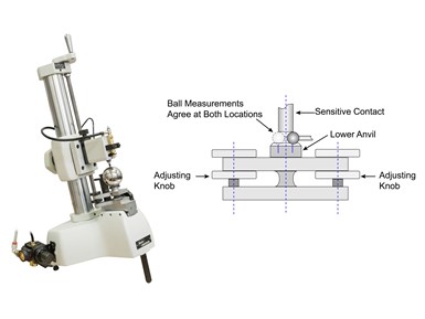
A robust comparator is necessary for accurate measurements. This diagram demonstrates a common setup when measuring balls.
Using frictionless measuring probes should ensure constant gaging pressure, high performance, and low hysteresis, promoting a precise millionth measurement. Furthermore, to ensure repeatable positioning of the ball, users should install a V-notched saddle on the anvil to locate the ball. Finally, users should tilt the whole gage backward so gravity secures the ball between the notch and the reference anvil before the user brings the sensitive contact into place to measure it. Users will need to set up and use the gage in a controlled environment appropriate for microinch measurements, taking steps to guard against contamination and thermal influences.
There are two schools of thought on the measurement setup: One is to force the ball between the contacts to “wipe away” dust and oil that could skew the measurement. Another is to retract the upper contact with a lifting lever before placing the ball on the stage to ensure consistent gaging pressure between trials and reduce stress on the mechanism. While research on the effectiveness of each is inconclusive, the majority of users lean toward the retraction method, positioning the probe once the ball is in place. This reduces stress on the sensitive contact and provides repeatable probe contact to the ball being measured.
How Do You Check Accuracy?
After preparing a precise setup, one may think measuring a ball is simple, but there is more to it than a single diameter.
When users specify a ball, they usually focus on its nominal diameter (D), meaning the value by which it is identified — think 0.5 inch or 12 mm. This diameter should lie within the range of its manufactured tolerance and correspond to the ball’s single diameter (Ds), which is the distance between two parallel planes tangent to the ball’s surface.
However, no ball is perfectly round or identical to another. When using balls as gage masters, it is important to establish the level of uncertainty. To accomplish this, individual balls are measured several times at random locations to find minimum and maximum diameters. The difference between these, known as ball diameter variation, is simply calculated as VDs = Ds max - Ds min.
Utilizing several additional parameters can help with quality control purposes. One parameter is ball mean diameter (Dm), the arithmetic mean of the largest and smallest single diameters of a ball, which is calculated as Dm = (Ds max + Ds min)/2. To account for production variation between units, manufacturers typically measure in lots. Lot sizes typically consist of 10 balls, but in some cases can be 50 or more. Calculations of lot mean diameter (DmL) and lot diameter variation (VDL) are based on the mean diameters of the largest and smallest balls in the lot, as follows:
DmL = (Dm max + Dm min)/2
VDL = Dm max - Dm min
All of the above are static measurements that users can perform using straightforward comparator gaging equipment. Bearing manufacturers, however, require more data to predict performance under dynamic conditions. These additional measurements can be performed using circular geometry (roundness) gages, which can generate least-squares circles, analyze waviness geometry in a velocity-proportional fashion, and perform harmonic analysis to predict the noise effects of part geometry at various speeds and under various loads. For machine shops that use balls mainly as measuring standards, precise comparator gages can provide all the data necessary to ensure accuracy.


Related Content

How to Choose the Correct Measuring Tool for Any Application
There are many options to choose from when deciding on a dimensional measurement tool. Consider these application-based factors when selecting a measurement solution.
Read More
Choosing the Correct Gage Type for Groove Inspection
Grooves play a critical functional role for seal rings and retainer rings, so good gaging practices are a must.
Read More
6 Machine Shop Essentials to Stay Competitive
If you want to streamline production and be competitive in the industry, you will need far more than a standard three-axis CNC mill or two-axis CNC lathe and a few measuring tools.
Read More
How to Calibrate Gages and Certify Calibration Programs
Tips for establishing and maintaining a regular gage calibration program.
Read MoreRead Next

How To Calibrate Your Calipers
If you’re interested in calibrating your own digital, dial or Vernier calipers, here are some steps to take to make sure it goes off without a hitch.
Read More
Tips for Choosing Filter Settings When Measuring Round Shapes
When interpreting measurement data, the correct filter setting is necessary to see the difference between surface roughness and part roundness.
Read More
Portable Surface Gaging in a Production Environment
Handheld portable surface gages are easy to use. But that doesn’t mean there aren’t challenges when scanning hundreds or even thousands of parts.
Read More