
Coolant’s Impact on Face Milling Aluminum
Testing shows that understanding the interplay among cutting speed, tool wear and cutting power can lead to more informed evaluation of metalworking fluids and more predictable machining.

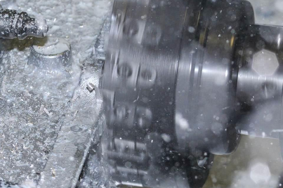
Un cortador de cartucho Tedimill de 6 pulgadas, de Ingersoll Cutting Tools, planea un múltiple de aluminio (imagen cortesía de Ingersoll Cutting Tools)
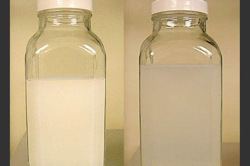
Los dos fluidos principales probados fueron el F1E (izquierda), una macro-emulsión con una apariencia blanca opaca, y el M70, una micro-emulsión con una apariencia traslúcida, debida a las gotas de menor diámetro de aceite suspendido. El último fluido superó al primero (imagen cortesía de Quaker Chemical Corp.)
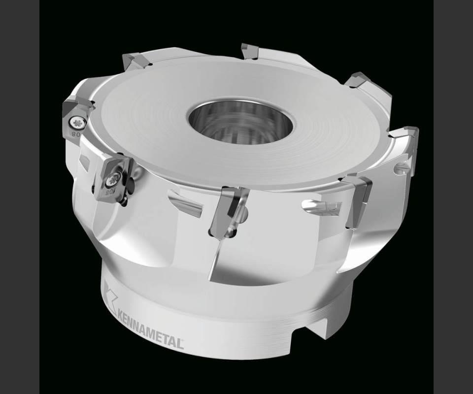
La herramienta usada en la prueba fue una fresa de planear de 3 pulgadas de diámetro con ocho insertos de Kennametal (imagen cortesía de Kennametal).

Figura 1. En cada velocidad de corte las diferencias en potencia entre los dos fluidos son mínimas. A medida que el corte continúa, las diferencias en la tasa de incremento de potencia se vuelven más claras (imagen cortesía de Quaker Chemical Corp.)
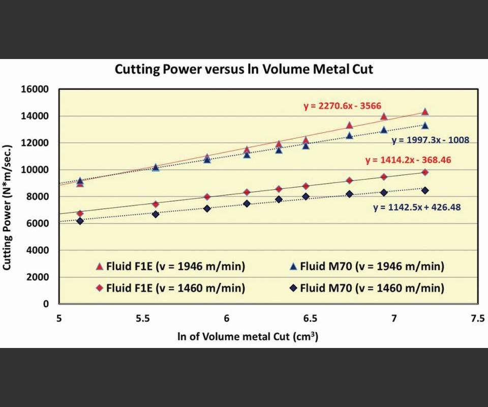
Figura 2. Al graficar la potencia de corte contra el logaritmo natural del volumen de metal cortado se obtiene una imagen clara – y una medida cuantitativa – de la tasa a la cual se incrementa la potencia con un desgaste continuado del inserto. La relación lineal entre estas variables abre potencialmente la puerta para predecir el desgaste del inserto y los requerimientos de potencia en cualquier punto en una rutina de fresado (imagen cortesía de Quaker Chemical Corp.)
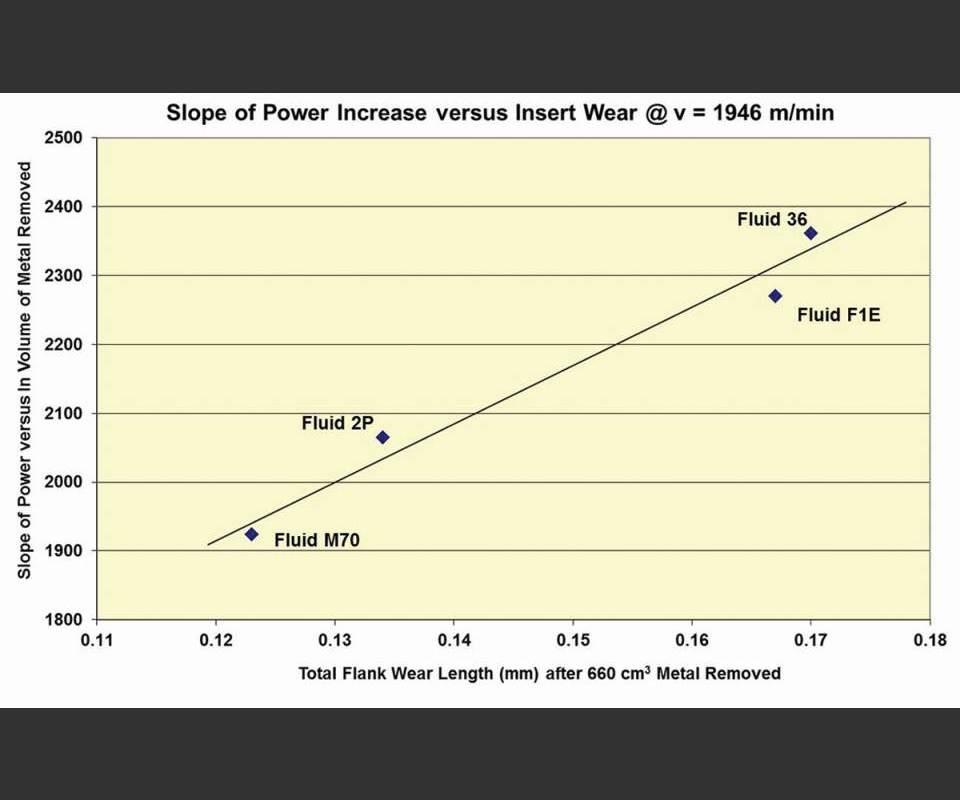
Figura 3. Al adicionar dos fluidos más y mediciones directas de la longitud del desgaste lateral a estas pruebas, se confirmó que los niveles de desgaste del filo de corte más altos corresponden a niveles más altos de potencia de corte requerida (imagen cortesía de Quaker Chemical Corp.)
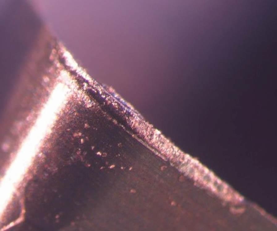
La medición de este inserto reveló una longitud de desgaste lateral de 0.123 mm. Aunque este inserto particular no experimentó adhesión de metal, otros sí lo hicieron (imagen cortesía de Quaker Chemical Corp.)


Manufacturers of parts like automotive engine blocks and cylinder heads mill a lot of aluminum. Typically, these operations involve taking light passes at the most aggressive speeds and feeds possible. The goal is to increase cutting speeds enough to boost productivity without exceeding the force and power limits of the machine and cutting tools. The better the understanding of the interplay of cutting speed, tool edge wear and required cutting power, and how the chosen metalworking fluid formulation impacts all of these factors, the more successful this endeavor is likely to be.
To that end, Quaker Chemical Corp. conducted a series of aluminum face-milling tests to assess the impact of different coolants on cutting power and cutting tool edge wear. With a fresh cutting tool, the tested coolants, as well as cutting speeds, made little difference on machining forces generated at the same cutting speed. However, the farther the tool’s progression in the milling operation, the greater the differences in the power required for effective machining with the different fluid formulations.


These results indicate the following:
- The influence of the metalworking fluid on cutting power is minimal with fresh, unworn inserts. Thus, the difference between two coolants’ impact on cutting power might not be noticeable until tool edges begin to wear.
- The influence of cutting speed on cutting power is also minimal with a fresh, unworn cutting edge.
- Power increase during aluminum milling is a direct result of cutting edge wear. The rate of that wear is directly influenced by both the cutting speed and the metalworking fluid used.
- The relationships among these variables are linear (cutting speed, cutting edge wear and cutting power all increase together). Armed with this knowledge, manufacturers can potentially predict the condition of the cutting edge at any point in the milling routine as well as the required power at other, untested cutting speeds.
Hitting the Lab
Testing focused primarily on two fluids, one micro-emulsion and one macro-emulsion, each diluted at 5 percent concentration in water with hardness of 100 parts per million. The primary difference between the two is the size of the suspended oil droplets. These measure more than 0.4 micron in diameter in the macro-emulsion, imparting an opaque, white appearance, and smaller in diameter for the translucent micro-emulsion.
The machine was a Bridgeport GX-710 three-axis VMC. The workpiece was a 203.2-by-228.6-by-38.1-mm block of aluminum 319-T6, a cast, heat-treated alloy containing copper (Cu), magnesium (Mg), Zinc (Zn) and Silicon (Si). The cutter was a 3-inch-diameter shell mill with eight inserts featuring 15-degree relief angles and 1.2-mm nose radii. It ran at an axial depth of 2 mm and radial depth of 50.8 mm. Each coolant formulation was applied throughout 28 climb-milling passes at two different cutting speeds, 6,096 rpm (1,460 m/min.) and 8,128 rpm (1,946 m/min.), for a total material removal volume of 1,321.6 cm3 per test. Feed rates at both speeds were 0.5 mm per revolution (0.0625 mm per insert per revolution).
Speed, Wear and Power
For this research, power measurements during cutting were obtained with a tool monitoring and adaptive control system. Test results are illustrated in the charts in the slideshow at the top of this article. As expected, faster cutting speeds drove machining forces higher. As described above, however, differences in cutting power between the two fluids were minimal with a fresh, unworn insert at the start of the milling operation.
At the start of the process, the properties of the workpiece material and the geometry of the cutting edge are the dominant factors impacting cutting power. Differences between metalworking fluid performance emerged only after insert wear began to change the cutting edge geometry. The choice of metalworking fluid directly impacted the rate at which this wear occurred and, by extension, the required cutting power at any given point in the milling operation.
One implication of this research is that a quick test might not be enough to understand the full impact of changing to a new type of coolant. Assuming a certain baseline performance level for the two fluids being compared, tests must run until the inserts wear to determine which formulation enables sustaining more aggressive cutting speeds for longer periods of time.
Another implication is the operational intelligence that can be gleaned by calculating the precise rate at which power increases with a particular cutting tool, coolant and material combination (the slopes of the lines in Figure 2). For example, the rate of power increase can be used to predict the condition of the insert at any given point in the milling operation. Similarly, power measurements taken at multiple cutting speeds can be used to derive the required power at other, untested cutting speeds.
Proving It Out
Whereas Figure 1’s X axis consists of raw data on material removal volume, Figure 2 uses the natural logarithm of this variable. Plotting the volume of material removed in this way results in a slope that represents the precise rate at which power increases with continued machining. This quantifiable measure is essential to predicting tool edge wear and cutting power at various cutting speeds. However, these data prove only that cutting power and material removal volume rise together. Confirming insert wear specifically as the driving force behind the power increase required additional testing (specifically, to correlate the slopes of the lines in Figure 2 directly with the insert wear that occurs during machining).
These tests added two additional fluids: another macro-emulsion and another micro-emulsion. Each of the four fluids was applied at a cutting speed of 1,946 m/min. until 660 cm3 of material was removed. This allowed sufficient time for abrasive wear, and in some cases metal adhesion, to progress on the inserts’ flank face surfaces. Flank wear measurements for the four fluids were then plotted against a parameter relating cutting power to volume of metal cut (specifically, the slope of the power versus the natural log of the volume of metal removed). As demonstrated in Figure 3, this confirmed the linear relationship between insert wear and the increased cutting power during machining.
Other Conclusions
Although test results cannot necessarily be extrapolated beyond aluminum milling, the research indicates that a micro-emulsion performs better—if the goal is to machine at the highest possible speeds. That’s because a tighter micro-emulsion with smaller-diameter oil droplets tends to remove heat more efficiently than a macro-emulsion and its relatively larger droplets. However, operations involving slower cutting speeds might favor a macro-emulsion and its comparatively greater lubricity.
Whatever the application, the best way to find the right coolant is to try different formulations in action. Understanding the relationships among cutting speed, tool wear and cutting power, as well as how metalworking fluids can impact these factors, is critical to making the right choice.
Based on an article by Robert Evans, Ed Platt and Andreas Wierschen, Quaker Chemical Corp., Metalworking Division Research Laboratory.


Related Content

How to Mitigate Chatter to Boost Machining Rates
There are usually better solutions to chatter than just reducing the feed rate. Through vibration analysis, the chatter problem can be solved, enabling much higher metal removal rates, better quality and longer tool life.
Read More
New Modular Tool Options for Small Spindle Milling
Tooling options have been limited for small spindle milling applications. Now modular, indexable systems are available that provide broad flexibility to get the right cutter for the job with less inventory and at lower cost.
Read More
Ceratizit's Updated Tooling Solutions Improve Machining Performance
The company has upgraded its EcoCut indexable inserts lineup, as well as introduced two new toolholding and workholding solutions.
Read More
Best Practices: Machining Difficult Materials
Cutting hardened steel, titanium and other difficult materials requires picking the right tools, eliminating spindle runout and relying on best practices to achieve tight part tolerances.
Read MoreRead Next

3 Mistakes That Cause CNC Programs to Fail
Despite enhancements to manufacturing technology, there are still issues today that can cause programs to fail. These failures can cause lost time, scrapped parts, damaged machines and even injured operators.
Read More
The Cut Scene: The Finer Details of Large-Format Machining
Small details and features can have an outsized impact on large parts, such as Barbco’s collapsible utility drill head.
Read More
