Sikorsky Aircraft took an unusually different approach on one recent product development project. Instead of settling on part designs and engineering the processes to produce them, the company looked at the capabilities of available machine tools in the market first, and then designed the parts accordingly. You might call it a new twist on the concept of Design for Manufacturability (DFM).
This approach guaranteed that the part design could, in fact, be processed. The problem with the usual approach is that the machine tool expected to do the job might not have the capability after all. In that case, the part design is impossible to process—an unwelcome discovery when staying on schedule and adhering to a budget are critical. However, reversing the order of design-the-part-then-match-the-machine is not so simple. For example, Sikorsky had to rethink how it worked with machine tool builders. In this case, only one builder in the five-axis machining center category seemed to have what the shop needed. This builder, Mitsui Seiki, had to draw on its penchant for collaboration and its willingness to address any limits of its technology to work with Sikorsky. On both sides, the level of commitment and support needed for this project was also extraordinary.
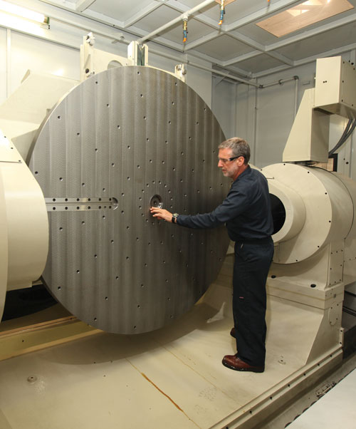
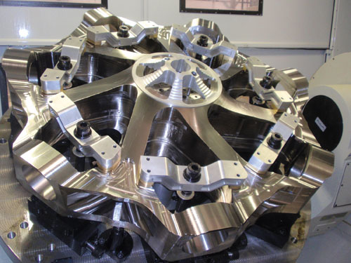
Early results have affirmed the validity of this experiment in DFM. The largest of Sikorsky’s three new five-axis Mitsui Seiki machining centers is now producing two of the biggest, most complex titanium components it has ever designed. One is a main rotor hub that measures 66 inches in diameter and weighs 2,450 pounds before machining. With the fixture, it weighs more than 10,000 pounds. The other is a rotating swashplate that measures 78 inches in diameter and weighs 1,450 pounds before machining. A high-torque spindle is one feature that is essential to machining titanium workpieces of this size. A 1,900-mm table, designed specifically for this application, also makes a significant difference in fixture design and rigidity.
“When the project launched, we had a general idea of what we needed in the optimum machine tool, but when we garnered detailed knowledge of the machine’s characteristics, we were able to use the optimum cutters, develop the right part fixturing and plot out proper setup procedures,” says Brian DeBlasi, Sikorsky’s manager of new product development. “Likewise, every piece of geometry was engineered around how the part was going to be machined on the five-axis machining centers. This was the vision long before the rotor head design was finalized, which was long before the individual part geometry was finalized. These engineering and processing steps would not have been intuitive if we didn’t have a clear indication of what these machines could do,” he says.
Mark Tuscano, a Sikorsky process engineer on the team, makes another point: “We acquired a new, one-of-a-kind machine tool, but our new approach around the process is something we intend to replicate on other projects in the future. This approach is the hallmark or our new Precision Components Technology Center.”
Keep Intellectual Property on the Property
A passion for aviation drove immigrant Igor Sikorsky to establish The Sikorsky Manufacturing Corporation in 1925 on Long Island, New York. The company later became The Sikorsky Aviation Corporation. In 1929, Mr. Sikorsky purchased land inStratford, Connecticut, and the company eventually became a subsidiary, and later a division of, United Aircraft Corporation, which evolved into United Technologies Corporation in 1975. Today, as Sikorsky Aircraft Corporation, the company is a world leader in the design, manufacture, service and repair of helicopters and fixed-wing aircraft.
Like many OEMs these days, the company routinely outsources about 74 percent of its manufacturing operations. It has several of its own facilities in the United Statesand around the world. However, when a long-time customer approached Sikorsky to develop a new type of proprietary aircraft requiring extra-large rotor components, the company decided to keep the project in-house at its Connecticut headquarters. “Production is one thing, R&D is quite another,” Mr. DeBlasi says. “Innovation is our foundation; it’s the core of who we are as a company. It’s also our future work. We had to keep that control because these parts are critical to the safety and performance of the aircraft. Further, as anyone in development knows, things change all the time. There is concurrent engineering throughout as the designs mature, and tight schedules are always in the mix. These types of parts are what we call our ‘family jewels,’ and we like to keep an eye on our jewels.”
Geometry Up in the Air
When Mr. DeBlasi first heard of the potential new aircraft project in 2005, no team dedicated to the project was in place. However, Sikorsky needed to react quickly to the preliminary data because it was the sole developer of the new aircraft. The design team wasted no time in modeling several main rotor head concepts. So although Mr. DeBlasi did not know what the total design configuration was going to be, he did know what it was going to look like, at least roughly. Sikorsky has been making parts like these for more than 70 years. “Think of a large, fancy doughnut,” Mr. DeBlasi says. He knew that it was going to be bigger than anything the company had ever built before. He also knew it would most likely be made of titanium, but that’s about all he knew.
Together, Mr. DeBlasi and Mr. Tuscano further explored the developmental aspects of the project. They assessed all the machines in the factory to determine if any of them could produce the new parts. They were told they could not use these machines because current production couldn’t be interrupted. Furthermore, none of the legacy machines had the size or the ideal capabilities for the entire family of rotor head parts, which included the main rotor hub, the stationary swashplate, the rotating swashplate, the sleeve horn and the tail rotor hub.
Subsequently, Mr. DeBlasi submitted an E-CAR (Electronic Capital Appropriation Request), the company’s standard cost and justification tool for a capital investment. Despite the lack of geometry details, Mr. DeBlasi and his team, which now consisted of 10 members, knew they needed a five-axis machine with a high-torque spindle and the capability to machine complex geometry and tough materials, accommodate great weight and hold tight tolerances. “We did a capacity analysis, so we knew we needed three machines initially and then an additional two shortly after,” Mr. Tuscano says.
At that point, it became clear to Mr. DeBlasi, Mr. Tuscano, and Senior Project Engineer Ken Catino that what they needed was essentially a Flexible Manufacturing System (FMS). The three engineers envisioned an FMS that could not only produce all of the new components, but also serve as a dedicated area for future development programs. The FMS might even provide additional capability to carry out regular production work.
“No longer were we talking about one machine, but really a mini factory within the factory,” Mr. Tuscano says. “We put together a matrix of all the machine tool manufacturers that quoted and we narrowed it down to two in each of our two equipment categories—five-axis machining centers and vertical turret lathes.”
Mr. Tuscano says Mitsui Seiki was on the short list for five-axis machining centers because of its reputation for accuracy, its experience in machining titanium, the machining capacity of its product lineup and its custom-engineering approach to machine tool building. Among the machine attributes deemed essential were a table that could accommodate the 78-inch-diameter rotating swashplate; a 50-taper, high-torque spindle with a bolt-on base to accommodate the unusually large cutters required to cut titanium; provisions for programmable, through-spindle coolant delivery to help break the chips; and a Fanuc control unit. Mr. Tuscano notes that choice of control units was important because most of operators were familiar with this brand, and the maintenance department stocked appropriate spare parts. He also wanted to avoid mistakes that might occur if different procedures (such as those for establishing offsets) were required for different types of control units.
The Power and the Partnering
When Mr. DeBlasi, Mr. Tuscano and Mr. Catino met with the builder’s group, they learned more about the specifications of the available machines. They also came to appreciate the level of understanding this builder had about machining titanium parts. For example, the machine tool must be stiff enough to consistently resist heavy cutting loads, thus maintaining volumetric accuracy. Also, the machine must have adequate spindle horsepower and torque as well as large servomotor drives on the ballscrews.
For the largest of the three machines, the specifications subsequently proposed by the builder included an X-Y-Z working area of 2,000 mm by 1,750 mm by 1,400 mm (78.7 by 68.9 by 55.1 inches) to accommodate the rotating swashplate; a custom A-axis pallet table that tilts from +20 to -110 degrees in 0.001-degree increments; and a B axis that rotates in 0.001-degree increments. Also specified was a 50-taper spindle with rotational speeds from 15 to 6,000 rpm driven by an AC 37 kW/30kW (50/40 hp) motor. The critical torque rating for this spindle is 3,332 Nm (2,457 foot-pounds). To increase the rigidity of the connection between the toolholder and spindle nose, the machine would include a BigPlus dual-contact spindle interface. Sikorsky specified and the builder provided automatic toolchangers that accommodate 360 cutting tools weighing as much as 30 kg (66 pounds) each and ranging in length to 650 mm (25.6 inches).
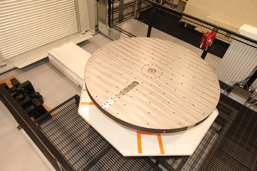
“We listened to each other and relayed a tremendous amount of detail, particularly as to how we wanted to fixture the parts,” Mr. DeBlasi says. When Mitsui learned that the main rotor hub and the fixture would weigh nearly 10,000 pounds before machining, the builder expressed concern about the likelihood of a 0.006-inch bearing sag when the table was in the negative 90-degree position. Unaccustomed to having a machine tool builder discuss limitations in its products, the Sikorsky engineers were surprised by this revelation. However, they were equally pleased to hear about the solution. Mitsui engineers designed special, 1,900-mm (74.8-inch) diameter pallet tables that could serve as fixture bases for two of the main rotor hub roughing operations. “Integrating the fixture and the table was creative and it enabled us to process the big rotor part on that machine,” Mr. Tuscano says.
Mr. DeBlasi points out that all parties included in implementing the FMS were willing to learn from one another. Both Mitsui Seiki and Phoenix, Inc., the VTL provider, became part of a collaborative engineering venture. “We were all tooling and planning the job based around the five-axis machining center. That’s what we considered the heart of the process and its success,” Mr. DeBlasi says.
The Birth of the Precision Components Technology Center
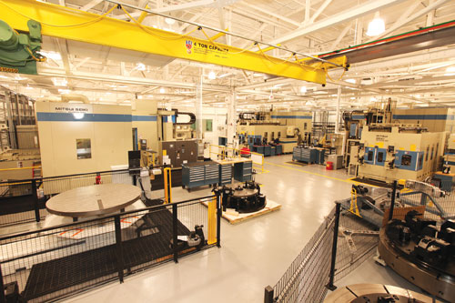
Once they established the scope of what they wanted to achieve and received all supplier quotes, Mr. DeBlasi, Mr. Tuscano and Mr. Catino presented the case to management for the capital expenditure. Ultimately, management approved an initial $20-million investment, which included reconstructing a 20,000-square-foot area in the factory. They dubbed this area the “Precision Components Technology Center.”
The center’s main manufacturing resources consist of:
- A Phoenix VTL, customized with a second ram. It features a 90-inch table, a BigPlus 50-hp CAT50 milling spindle and a five-station pallet pool.
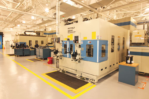
- One five-axis machining center for 1,900-mm pallets.
- Two five-axis machining centers for 1,200-mm pallets.
- Load/unload stations.
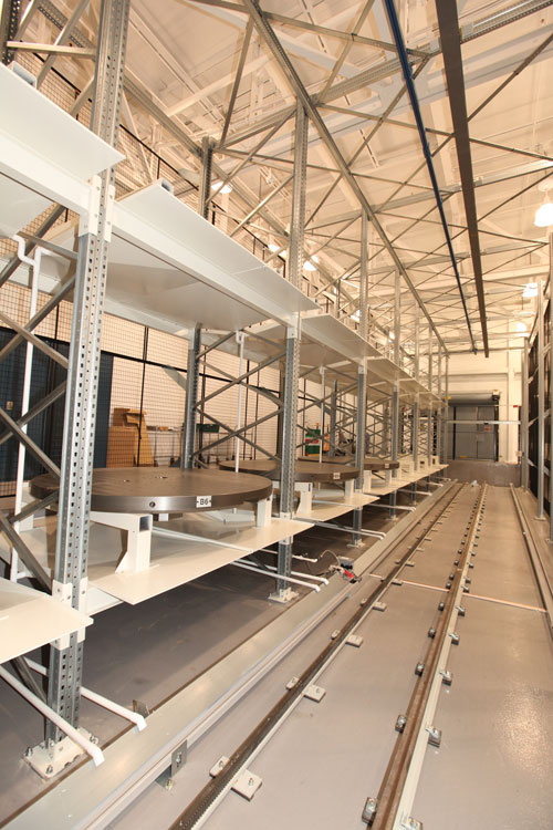
- Two Fastems automatic pallet handling systems that serve the machining centers. With accommodations for 42 pallets for the mid-sized machining centers and 24 pallets for the large machining center, this was the second largest such installation to date.
Under an additional capital appropriation, a large Zeiss CMM stands in a separate, 4,500-square-foot room across the hall. Both rooms are climate-controlled.
When the approval was given, Mr. DeBlasi formulated a personnel plan. The development and implementation of this plan were critical to the project’s overall success, although a detailed explanation is beyond the scope of this article. Mr. DeBlasi’s kick-off meeting; his approach to creating a team; his team charter; his guidelines for working together and the concept of “shared space;” his flow chart of schedule risks and mitigations; and other cohesive organizational approaches were recognized as major contributors to the project’s effectiveness. “We brought a diverse group of 15 people together, including representatives from NC programming, fixture design, cutting tool engineering, process engineering and quality control,” Mr. DeBlasi says. He attributes the effectiveness of this team to its ability to work together without rivalry or territorial concerns.
Part and Fixture Designs Take Shape
While the machines were being built and the old fabricating area of the factory was being refurbished, the team finalized part geometry; fixture design; process flow charts; machining and automation software programs; and material handling procedures. Once the process for the new components was established, other aspects of manufacturing them could be fine-tuned accordingly. Process engineers reviewed the CATIA solid models of the parts and studied the corresponding machining operations, while the design associates completed detailed work on part geometry. At this point, the advantages of knowing the machine tool capabilities during this final design phase became apparent.
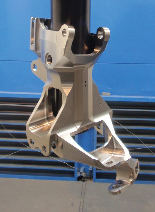
For example, the first iterations of the main rotor sleeve design were fairly simple. However, an analysis of the rough design of the rotor head parts indicated that the entire assembly would be grossly overweight unless changes were made. The design team considered ways to reduce the weight. They recognized that for an assembly such as a rotor head, one of the easiest ways to do this is to eliminate fasteners by combining multiple components into a single, monolithic configuration.
At first, some of the proposed monolithic combinations involving the main rotor sleeve, damper bracket and pitch horn components were rejected as too complex to machine. However, by combining these components, Sikorsky design engineers could eliminate part fretting at bolted joints and thereby reduce much of the assembly hardware and weight.
Fortunately, with the five-axis capabilities of the machining centers, machining the new combined part was a not a problem. “That’s a good example of how knowing what the machine can do—the process—guides option,” Mr. DeBlasi says. “Another good example is the main rotor hub. We were able to remove several steps in a pocket and, in this case, make it much simpler to machine. He adds that the rotating swashplate, the largest diameter titanium part ever made at Sikorsky, also underwent design revisions to remove several ribs and closed pocket configurations that would have been difficult to machine because of the required cutter geometry.
And so it went. The team systematically analyzed each part for manufacturability and tweaked the design based on process knowledge. Likewise, the team based fixture design on the process, too, to avoid clearance issues and maximize clamping effectiveness.
Once the part designs were as firm as they can be in an R&D scenario, Mr. Tuscano and his team used the CATIA models to create “process storyboards” showing each step in the machining process. Fixture designers then followed the storyboards to design the fixtures for each step in the process. “Their directive was simple but the task was complex. I asked them to build a fixture that would hold the workpiece yet make surfaces accessible for machining,” Mr. Tuscano says.
Each operation requires a different fixture, or a flipping of the part in the same fixture as it is processed through the FMS. Along with the necessary precision, the fixture designs incorporate integrated hydraulic arbors to ensure that the part locations are perfectly on center at each subsequent operation. The arbors promote repeatability during loading and provide additional holding power, thus enabling use of fewer clamping devices and creating greater access for machining.
The FMS in Action
The procedure for the main rotor hub serves as an example of how the FMS operates. The first operations on the hub forging are performed on the VTL, where both sides of the part are rough turned and some faces are rough milled. The milled flats are qualified, as is the center bore diameter. These steps give the part profile its initial shape. Next, the part moves to the large machining center, which mills away a total of 1,053 pounds of material to establish the various pockets and arm profiles. The workpiece then returns to the VTL for final turning of the inside diameter and arms. Then, it goes back to the machining center for finish machining.
The most critical tolerances are encountered at this stage. According to Doug Ventimiglia, the hub’s NC programmer, the shop is holding 0.005-inch parallelism, 0.002-inch on diameters and true positions of 0.005 inch. “It is important to note that we also applied design-for-manufacturability techniques extensively to minimize requirements for close-tolerance work. We did this mainly to take pressure off the people, not the machines. The machines can do it day in, day out. In fact, we routinely exceed specified tolerances because that’s what the process yields,” Mr. Ventimiglia says.
All of the machines have “zero” setup capabilities via dedicated part load/unload
stations that are tied to the pallet transfer station. This means that the machines can run while fixtures and parts are being loaded at the dedicated loading stations, thus maximizing productivity.
Going Forward
In February 2011, the center produced the first sample run of the final main rotor hub design. Naturally, the team is proud of the Precision Components Technology Center and what it represents for the future of the company. Members of the team believe the company is more secure because proprietary technology and intellectual property never go unprotected. A renewed commitment to maintaining ownership of critical know-how means understanding literally every detail about these parts and mastering the intricacies of how to make them.
“We set out to create a process for R&D prototype work, and what has emerged is actually a production model that is flexible enough to handle whatever opportunity we can attract. The model can be duplicated in our other facilities,” Mr. DeBlasi says. He adds that he learned the Japanese concept of “good business” (which essentially means “mutual trust”) from the Mitsui Seiki representatives and associates he met while visiting their factory. “That’s what the Precision Components Technology Centerrepresents at Sikorsky—good business,” says Mr. DeBlasi. “It all came together because of that concept. How we worked together as a team, how we collaborated with our suppliers, and how it began with a customer who believed in our ability to innovate all flow from it.”