
Different Directions In Machining Center Motion
Some machining centers have begun to appear that use resultant motion in less elaborate ways. That is, these machines use the resultant motion of different elements moving in different directions to achieve the motion along X, Y or Z, but they do so within machining center designs that are considerably more like standard machines.
.jpg;width=70;height=70;mode=crop;format=webp)


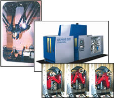
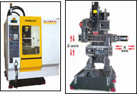
These two machining centers might be thought of as cousins to the hexapod (top left), but only in the sense that they use resultant motion to define at least one linear axis. In the Genius 500 horizontal machining center (top right images), the linear motors that move up and down in Y also produce the X-axis motion whenever they move separately, causing the coupler between them to shift. With no motor pushing in X, more of the machine’s force is directed downward instead of from side to side. In the S-500A "relative motion" vertical machining center (below), the table and the tool move toward one another simultaneously. The feed rate and acceleration result from the sum of these two movements.
These two machining centers might be thought of as cousins to the hexapod (top left), but only in the sense that they use resultant motion to define at least one linear axis. In the Genius 500 horizontal machining center (top right images), the linear motors that move up and down in Y also produce the X-axis motion whenever they move separately, causing the coupler between them to shift. With no motor pushing in X, more of the machine’s force is directed downward instead of from side to side. In the S-500A "relative motion" vertical machining center (below), the table and the tool move toward one another simultaneously. The feed rate and acceleration result from the sum of these two movements.
The traditional machining center has axis motors that push in one direction or the other along X, Y and Z. In the 1990s, all of us who attend machine tool trade shows learned that this wasn’t the only way to design the machine. A variety of builders brought out "hexapod" and/or "parallel kinematic" machines in which a daddy-longlegs arrangement of linear-motion members used CNC interpolation to achieve precisely the same X-Y-Z motion as a standard machine.
These novel machining centers make for attention-grabbing live demonstrations at trade shows. In fact, these eye-catching machines began to appear at trade shows not long after the use of attractive female models at these shows began to decline—almost as if some different means of capturing attendees’ attention had to be invented. However, real-life users of these machines remain uncommon to say the least. While a machine tool buyer may notice a trade show booth because of the complex motion of one these machines, that buyer is still more likely to spend money on a machine that has a more standard design.


But now, an important development may go unnoticed beneath the presence of these more elaborate machines. Some machining centers have begun to appear that use the same fundamental idea—resultant motion—in a less elaborate way. That is, these machines use the resultant motion of different elements moving in different directions to achieve the motion along X, Y or Z, but they do so within machining center designs that are considerably more like standard machines.
Here are just two examples. One is the line of "relative motion" machining centers from Olympic Seiki (represented in the United States by Vigor Machinery Company). With these machines, it is not the tool motion or table motion alone that provides the machine’s traverse; it’s the tool and table together. In the X and Z axes, the ballscrew simultaneously moves both table and tool in opposite directions. The feed rate of the tool relative to the part is the sum of the traverse rates of both elements. Ditto for the acceleration. On smaller machines in this line, the resultant acceleration is 2G. In addition to speed, another benefit may be stability. With mated elements moving in symmetry, says the company, the design of this machine favors dynamic balance.
Another machine design taking advantage of resultant motion is the "Genius 500" horizontal machining center from Cross Hüller. On this machine, the X-axis motion—that is, the side-to-side motion—comes from elements that move up and down along the Y direction. The mechanism for this is an inverted V-shaped coupler that carries the spindle. This inverted V straddles between two sets of linear motors that run up and down. When the linear motors move together at the same speed, the result is pure Y-axis motion. But when the linear motors move differently, the difference causes the coupler to pivot, providing the motion in X.
As a result, there is no need for a motor to push along the X axis on this machine. Therein lies a benefit of the design. Whether the motion is X or Y, the force of the axis motors goes along the direction of gravity, where the machine is well-supported (by the floor). Thus the machine can move the tool rapidly throughout the X-Y plane, with none of the motion of the axis motors directly producing sideways forces.


Related Content

Threading On A Lathe
The right choices in tooling and technique can optimize the thread turning process.
Read More
Volumetric Accuracy Is Key to Machining James Webb Telescope
To meet the extreme tolerance of the telescope’s beryllium mirrors, the manufacturer had to rely on stable horizontal machining centers with a high degree of consistency volumetric accuracy.
Read More
Watchmaking: A Machinist’s View
Old-world craftsmanship combines with precision machining on a vertical machining center and Swiss-type lathe to produce some of the only U.S.-made mechanical wristwatch movements.
Read More
10 Things to Know About Creep-Feed Grinding
Because of the high material removal rate creep-feed grinding can deliver in challenging materials, grinding might not be just the last step in the process—it might be the process.
Read MoreRead Next

The Cut Scene: The Finer Details of Large-Format Machining
Small details and features can have an outsized impact on large parts, such as Barbco’s collapsible utility drill head.
Read More

3 Mistakes That Cause CNC Programs to Fail
Despite enhancements to manufacturing technology, there are still issues today that can cause programs to fail. These failures can cause lost time, scrapped parts, damaged machines and even injured operators.
Read More