
Dimensional Inspection With A Digital Camera
Using an off-the-shelf digital camera, this system uses photographs to obtain 3D measurement data.
.jpg;width=70;height=70;mode=crop;format=webp)


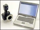
Photogrammetry takes dimensional measurements using digital photography. A new system employs an off-the-shelf digital camera.
Photogrammetry takes dimensional measurements using digital photography. A new system employs an off-the-shelf digital camera.
A picture is worth a thousand words. Could it also be worth a thousandth of an inch?
Through the technology of “photogrammetry,” it is now possible to use a standard digital camera as a coordinate measuring device comparable to a CMM. While photogrammetry itself is not new, its application to industrial measurement has previously required a special camera engineered for this use. Now, Geodetic Systems (Melbourne, Florida) has introduced a less expensive photogrammetry system using an off-the-shelf digital camera from Nikon that is outfitted with a special lens.


Photogrammetry refers to using photographs to obtain 3D position information, through software that compares multiple photographs at different angles. Photogrammetry is what surveyors use to create 3D topographical maps. At much closer range, the same technique can determine XYZ coordinates of workpiece features to accuracies as tight as 0.001 or 0.002 inch across a 10-foot object.
The actual accuracy depends on a variety of factors, one of which is the number of photographs taken. In theory, just two images can generate a photogrammetric measurement. In practice, particularly in an industrial setting, users take six, eight or more photographs in order to let the system better calibrate itself and compensate for errors.
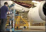
Big parts make the most sense for this measurement approach, particularly those parts so big that a typical machine-shop CMM can’t inspect them. One advantage photogrammetry offers over many portable measurement devices is that the approach is largely unaffected by movement or vibration of the part.
Applying photogrammetry is not quite as easy as just snapping photos. To measure features, the system measures points of illumination. Users apply reflectors or pinpoints of light in order to illuminate the points they want to measure. Geodetic Systems vice president Gary Johanning says there are a variety of options for doing this. They include:
- Stick-on targets, or reflective stickers that the user attaches to the part.
- Hard targets, or reflective hardware accessories. These might take the form of a cap that fits over a corner of the workpiece or a shank that fits into a hole. These targets are measured off-line so that the relationship between the reflector and the measured feature beneath it is precisely known.
- A grid of white-light dots projected onto the part. Rather than measuring holes or edges, this approach lets photogrammetry map the slope or contour of an angled or curving surface. The accessory that projects this grid of lights onto the part resembles a bazooka, and in certain applications, its use can also allow photogrammetry to track the movement of dimensional features that are changing.
Yet another approach to getting points of light into the photos could involve probing. The feature measured could be touched with a standard coordinate measurement probe that has reflectors attached. This approach requires two cameras working in unison, both of them synchronized with the probe.
Adding illuminated points to the photos through one of these approaches is an essential part of photogrammetric measurement, as is the computer that compares and analyzes the photographs. Thus, photogrammetry involves a kit instead of just a camera, but the kit is still quite portable. It can easily be carried to the location on the shop floor where some heavy part—such as a large mold or an aircraft component—waits to be inspected.


Related Content

A Case for Combining Workholding with Optical Scanning
Automotive dies and die inserts are often complex, one-off parts with little room for error. Integrity Tool's investments in modular workholding tools and 3D optical scanning have allowed the company to create niche capabilities for its CNC machined parts.
Read More
How to Calibrate Gages and Certify Calibration Programs
Tips for establishing and maintaining a regular gage calibration program.
Read More
Ballbar Testing Benefits Low-Volume Manufacturing
Thanks to ballbar testing with a Renishaw QC20-W, the Autodesk Technology Centers now have more confidence in their machine tools.
Read More
What Should Machinists Know About In-Machine Probing?
In-machine probing doesn’t reach the power of CMMs but can still be useful for pre- and mid-process control, as well as for “rough screening” of parts.
Read MoreRead Next


The Cut Scene: The Finer Details of Large-Format Machining
Small details and features can have an outsized impact on large parts, such as Barbco’s collapsible utility drill head.
Read More