
Direct Edge Finding Via Laser
A laser edge finder offers a direct method for locating workpiece edges that can save setup time.
.jpg;width=70;height=70;mode=crop;format=webp)
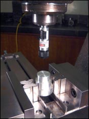
This non-contact laser edge finder projects a small laser dot to perform functions such as aligning a vise or finding the center of a round workpiece.
This non-contact laser edge finder projects a small laser dot to perform functions such as aligning a vise or finding the center of a round workpiece.


Conventional electronic or mechanical edge finders are commonly used during machine setup to position the spindle’s center line at the edge of a workpiece. This is considered an indirect positioning method. That’s because in order to locate the spindle’s center line at the edge, an operator must move the table an amount equal to the finder’s radius once the finder contacts the workpiece.
SDA Manufacturing, located in Piedra, California, says its Laser Center/Edge Finder offers a direct method for locating workpiece edges that saves setup time. When installed in a drill’s chuck or mill’s spindle via a collet-style tool holder, the laser directs its beam toward the worktable. The laser’s dot shows the actual position of the spindle’s center line relative to the workpiece, vise or fixture. This visual referencing allows operators to easily position the spindle at specific location points, workpiece centers, centers of holes or scribed lines. It also enables them to quickly align vises; set angular mill head angle; and center indexers and rotary tables.


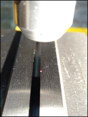
The laser, housed in 6061 aluminum, has accuracy repeatability of approximately 0.001 inch (0.02 mm). It can be positioned 1 to 12 inches away from its target using a standard polarizing attachment that focuses/minimizes the laser’s dot size. The Class IIIa laser device is powered by three 1.5-volt alkaline camera batteries that are said to last from six months to a year, depending on amount of use. The laser functions using a simple on/off switch. After use, it can be turned off and then stored in the machine’s ATC just like any other tool.
The standard Laser Center/Edge Finder is 3.375 inches long with a 0.75-inch diameter. It is available in shank sizes of 0.375 inch, 0.5 inch or 10 mm. A mini model measures 2.75 inches long, has a 0.75-inch diameter and shank sizes of 0.25 or 6 mm. The company offers a wet-cabinet version that is designed for use in machines that use coolant. It has the same dimensions as the standard unit, but is available only with a 0.5-inch shank. Once the laser is turned off after use, a vinyl boot can be slid over the device to seal and protect it from moisture.
Here’s how shops might put the Laser Center/Edge Finder to use: To measure material size or the width of a hole on a mill, locate the edge of the workpiece or hole with the laser and then null the machine’s digital readout (DRO). Move the table so that the laser reaches the opposite edge; the feature size will be indicated on the DRO. To locate the center of a hole, divide the hole’s measured diameter in half. Next, move the table that distance in the X axis toward the center of the hole and null the DRO. Finally, the move the table in the Y axis until the laser reaches the edge of the hole and then reverse the amount of the hole radius in the Y axis. That positions the spindle at the center of the hole.
To align a vise, load the vise in the approximate position and snug one of its hold-down bolts. Next, maneuver the table in X and Y axes until the vise jaws and laser dot are aligned and then secure all the hold-down bolts.
To center a workpiece in a lathe’s four-jaw chuck, place the laser in the tailstock chuck and loosen and tighten the jaws until the laser dot appears on the center punch mark or intersecting scribe lines. To return a tailstock to its center position after off-center taper-turning operations, install the laser in the headstock chuck and place a live or dead center in the tailstock. Move the tailstock so the center is close to the laser and adjust the tailstock side screws until the laser dot aligns with the center’s tip.


Related Content

How to Choose the Right Cut Off When Measuring Roughness
Measurement results for surface finishing parameters can vary depending on the filter parameter (Lc), also known as the cutoff.
Read More
Understanding Errors In Hand-Held Measuring Instruments
Different instruments (and different operators) are prone to different errors.
Read More
How To Calibrate Your Calipers
If you’re interested in calibrating your own digital, dial or Vernier calipers, here are some steps to take to make sure it goes off without a hitch.
Read More
Determining Out-of-Roundness at the Point of Manufacture
George Schuetz, Mahr Inc.’s Director of Precision Gages, offers these techniques for measuring roundness on the shop floor.
Read MoreRead Next

3 Mistakes That Cause CNC Programs to Fail
Despite enhancements to manufacturing technology, there are still issues today that can cause programs to fail. These failures can cause lost time, scrapped parts, damaged machines and even injured operators.
Read More

The Cut Scene: The Finer Details of Large-Format Machining
Small details and features can have an outsized impact on large parts, such as Barbco’s collapsible utility drill head.
Read More