
Does Your Grinder Have The Shakes?
Poor results from cylindrical grinding may be traceable to harmful dynamic forces coupled to the wheel/workpiece interface. A new system of sensors/actuators is helping detect the causes—and leading to a cure.


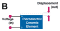
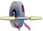
Figure 5. When you look at the relationship between wheel rotation and the dynamic forces coupled to the workpiece, the critical role of the workpiece supporting structures becomes evident.
Figure 1. The basic configuration of the typical OD cylindrical plunge grinder hasn't changed much over the years. Many older machines are still in production.
When you're last, you don't get a second chance. That's often the way it is with grinding. Grinding is frequently that last operation performed on a workpiece. The final shape and surface finish of the part depend on this operation. Meeting stringent specifications and holding tight tolerances often hinge on the grinder—and the value added by every prior operation is at stake.
There are thousands and thousands of cylindrical grinders at work today. The cylindrical grinder is one of the most important and most common grinding machines, largely because cylindrical grinding is an efficient and effective method of achieving exceptional roundness and surface finish. Roundness of 0.0004 inch TIR and finishes to 8 microinch rms are typical, but much tougher specs are becoming more common.


However, as this base of installed machines grows older, supporting the growing number of applications for high quality cylindrical grinding will become more difficult—and more expensive. A common problem with older grinders is that component wear is likely to cause increased vibration levels. Excessive vibration is quickly translated into degraded grinding performance. Workpiece quality suffers. Costs rise.
These problems are difficult to diagnose and treat on the shop floor. New techniques to monitor grinding forces are helping the industry understand grinding better. A clearer picture of what's happening during the grinding process is beginning to emerge. More important, these insights are pointing to developments that promise to help overcome the negative effects of unwanted dynamic forces at play in cylindrical grinding.
The Problem With OD Cylindrical Plunge Grinders
Plunge grinding processes are extremely complex and a complete understanding goes well beyond everyday operations on the shop floor. Countless variables including wheel materials, wheel loading and dressing, workpiece metallurgy, work drive mechanisms, workholding methods, coolant types, feeds and speeds, machine stiffness and age, way surface condition, center conditions and floor vibrations all influence the quality and throughput of finished parts.
Handbooks filled with sage advice are available to assist the machine operator in resolving grinding problems. However, the composite sum of these grinding parameters creates static and dynamic forces at the workpiece/grinding wheel interface, which help or hinder performance. When these forces are understood and controlled, better part throughput and surface quality will result.
What Force Monitoring Reveals
A typical OD cylindrical plunge grinder, circa 1970, is illustrated in Figure 1, at right. The familiar head and tailstock housings, wheel slide assembly and manual controls have remained relatively unchanged for decades. A grinding force time history (Figure 2) illustrates the normal grinding force between wheel and workpiece for a 0.0013-inch/second plunge into a hardened, plain carbon steel workpiece through initial infeed, plunge and sparkout. This figure reveals the complex and dynamic nature of the interaction between the wheel and workpiece. If the many transient forces represented by vertical lines in this plot can be controlled, then surface errors created by them in the wheel and workpiece can also be greatly reduced.
Sources Of Excessive Vibration
Because no metal finishing platform is perfect, random and forced vibrations are present in all plunge grinding operations. The magnitude and frequency of these vibrations vary greatly, but are generally attributed to the many structural components of the system. These sources include:
- Imbalances in the mass of the grinding wheel, workpiece, hydraulic pump, or other components.
- Spindle bearing wear and/or gear mesh vibrations.
- Coolant contamination and spray pressure fluctuations.
- Transient events such as a forklift truck driving by occasionally.
Figure 3 represents background measurements of a typical OD cylindrical plunge grinder to assess the contribution of various machine components. The noise level for a headstock Y axis (normal to the grinding wheel axis of rotation) sensor are reasonably low with all components turned off. However, the noise levels increase considerably when the hydraulic pump is turned on, indicating a high degree of coupling exists between the hydraulic pump and the machine structure. Additional increases in the noise levels are observed with the powering of the grinding wheel as well as the workpiece. High noise levels, which can be thought of as unwanted structural vibration, are harmful to the metal finishing process and should be avoided.
Modeling grinding vibration is a technique used to study and understand the process by which force is used to remove metal from the surface of the workpiece.
Random and forced vibration sources influence part infeed causing a disturbance in the machine structure. This process is known to create surface errors in the wheel and workpiece that include out-of-roundness, waviness, lobing, and chatter. When surface errors on the wheel or workpiece occur at a frequency that matches a system resonance, they can cause regeneration.
The grinding process becomes unstable and the magnitude of the forced vibration increases over time. All grinding processes are potentially unstable. What varies is the rate of chatter buildup and dissipation during the workpiece finishing cycle. Understanding the source of these unwanted vibrations is the first step in developing a practical solution to minimize their effect on the finished workpiece.
Further modeling suggests a relationship between the grinding zone (elastic contact between wheel and workpiece) and other components that make up the grinding machine.
Figure 4 illustrates a grinding machine simulation model. Key parameters in understanding component interaction include grinding wheel infeed mechanisms, machine stiffness, sources of unwanted vibration coupled to the machine stiffness, and the wheel/workpiece elastic interface.
Any practical solution to noise reduction in this system must consider these common relationships when preventing harmful forces from coupling into the grinding zone.
Counteracting Harmful Grinding Forces
Fixes for random, forced and regenerative vibration include:
- Identifying and removing imbalance/forcing functions in the machine system.
- Isolating the grinding machine from floor and other sources of outside vibration.
- Increasing structural stiffness to reduce amplitude of harmful vibration.
- Utilizing "active force control" mechanisms to counteract unwanted vibrations that cannot be eliminated through passive means.
Dynamic balancing systems have been very effective in eliminating periodic disturbances associated with wheel imbalance. Passive isolation platforms (such as shock-absorbing pads built into the mountings under a machine) are also popular in decoupling floor vibrations from the machine structure. But in most cases, it is not practical to remove all harmful forcing functions from the grinding machine. This situation exists because many of the sources of harmful vibration actually emanate from the grinding machine itself. Examples include hydraulic pumps, drive dogs, and worn spindle bearings, just to name a few.
Because removable centers are used to support the rotating workpiece against the grinding wheel, the concept of attacking the vibration problem at the workpiece support interface is a practical one. Regardless of the source of unwanted vibration, its structural transmission can be measured and compensated at the center support, permitting the interaction between the wheel and workpiece to continue uninterrupted.
Figure 5 (at right) shows the relationship between wheel rotation and normal vibration forces that couple into the grinding process via the structure supporting the workpiece. An "active" system in which the components are imbedded within the removable centers can measure dynamic forces (sensors) and compensate (actuators) to optimize the environment in which metal finishing takes place.
Dead Versus "Active" Centers
Centers are used to support the workpiece against the wheel during grinding and sparkout. Because unwanted machine motions couple into this process, the center supports are ideal locations to measure and compensate effectively for these harmful vibrations. Piezoelectric-based sensors and actuators have proven highly effective for this task.
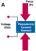
Solid state piezoelectric technology is mature, compact and exhibits extremely fast signal response. Small piezoelectric sensors are capable of measuring forces in excess of 300 pounds. Typical grinding forces on small engine components, for example, do not exceed 50 pounds. Small piezoelectric actuators generate forces greater that 250 pounds and provide static/dynamic stroke ranges exceeding 50 microns (0.002 inch). Most harmful grinding machine vibrations are no larger than 10 microns (0.0004 inch) in amplitude. When piezoelectric technology is integrated with conventional dead centers, the resulting solution is called an "active" center because this hybrid component has the ability to actively measure and correct harmful grinding forces during metal finishing.
EDO Corporation, Electro-Ceramics Division (Salt Lake City, Utah) has developed an active force control product line for the grinding industry, based on this technology. ENFORCER is the name of the initial entry and its release to the market is scheduled for the first quarter of 1999. Extensive testing of this product has provided a wealth of documentation verifying that the underlying concept of "active" centers is sound.
The "active" center approach to isolating harmful machine vibrations is illustrated in Figure 6. Removable "active" centers are installed in a manner identical to dead centers. These devices detect grinding forces and provide dynamic force compensation to minimize harmful machine vibrations from causing errors in the surface of the workpiece. This operation is performed using force control algorithms and a high speed digital single processor (DSP) controller.
As an example of "active" center effectiveness, a two-channel active force control system was installed on an OD cylindrical plunge grinder used to finish hardened hydraulic spool components. Figure 7 illustrates three distinct stages of this evaluation: Stage I (t = 0 to 170 seconds) shows zero force levels prior to wheel/workpiece contact. Stage II (t = 175 to 290 seconds) shows uncontrolled dynamic forces with significant peak-peak force amplitude and large variations in average grinding force. (Note: In the top trace, the control system detects the start of plunge grinding at t = 178 seconds.) Finally, Stage III (t = 290 to 480 seconds) shows controlled grinding forces with an infeed speed change at t = 375 seconds. The benefit provided by the ENFORCER using retrofittable "active" centers is significantly reduced dynamic force levels at the wheel/workpiece interface.
Nothing To Shake About
Does your grinder have the shakes? It doesn't have to. Emerging technology within the U.S. industrial base is providing advanced capabilities to improve the performance of new and existing metal finishing operations. The plunge grinding process is extremely complex but with new tools such as real-time force measurement and compensation, we can and will do better. U.S. technology and innovation still leads the world. With the new century fast approaching, we must adopt every manufacturing advantage at our disposal to maintain the accelerating pace of world manufacturing technology.
About the author. Gordon Cook is Design Engineering and New Product Development Manager at the Electro-Ceramics Division of EDO Corporation in Salt Lake City, Utah. The illustrations in the article are based on graphics prepared by Christine Glassey, EDO Publications and Communications Specialist.


Related Content

Grinding Wheel Safety: Respect The Maximum Speed
One potential source of serious injury in grinding comes from an oversight that is easy to make: operating the wheel in an over-speed condition.
Read More
A New Milling 101: Milling Forces and Formulas
The forces involved in the milling process can be quantified, thus allowing mathematical tools to predict and control these forces. Formulas for calculating these forces accurately make it possible to optimize the quality of milling operations.
Read More
Understanding Swiss-Type Machining
Once seen as a specialty machine tool, the CNC Swiss-type is increasingly being used in shops that are full of more conventional CNC machines. For the newcomer to Swiss-type machining, here is what the learning curve is like.
Read More
Volumetric Accuracy Is Key to Machining James Webb Telescope
To meet the extreme tolerance of the telescope’s beryllium mirrors, the manufacturer had to rely on stable horizontal machining centers with a high degree of consistency volumetric accuracy.
Read MoreRead Next


3 Mistakes That Cause CNC Programs to Fail
Despite enhancements to manufacturing technology, there are still issues today that can cause programs to fail. These failures can cause lost time, scrapped parts, damaged machines and even injured operators.
Read More
The Cut Scene: The Finer Details of Large-Format Machining
Small details and features can have an outsized impact on large parts, such as Barbco’s collapsible utility drill head.
Read More