
Getting The Most From Creep-Feed Grinding
No other process can do what creep-feed grinding can do. Recent tests show even more can be gained by optimizing every element of a creep-feed system.


Fig. 4—With electroplated wheels, there is a clear relationship between abrasive grit size and surface finish. The smallest grit produced the smoothest surface.
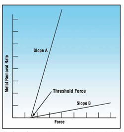
Fig. 2—With a sharp cutting wheel, small increases in grinding forces cause metal removal rates to jump up, as in Slope A. With a dull-cutting wheel, increasing the grinding forces only raises the removal rates a little, as in Slope B.

Fig. 1—This setup was used for all experiments on creep-feed grinding.
Fig. 3—The grinding wheel rotates in opposite directions to create up or down cutting.
Fig. 5— When plunge dressing a creep-feed wheel, rotating the diamond roll in the right direction and at the right speed depends on the type of wheel and the desired surface finish.
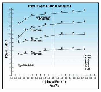
Fig. 6—In this graph, the four curves represent results obtained at progressively higher metal removal rates.
More and more manufacturers are realizing that creep-feed grinding helps reduce costs. New technology allows it to do more and get better results. Creep-feed grinding can produce higher quality parts and do so in less time than other processes, thanks to new abrasive grains, better machine tools and improved methods.
Creep-feed is essentially a process to remove large amounts of stock in a single pass of the grinding wheel—and then to produce the prescribed surface tolerances and finishes in a second pass. Compared to other grinding processes, creep-feed grinding involves faster cycle times, higher metal-removal rates, better dimensional accuracy and fewer burrs because of the relatively larger areas of conformity between the grinding wheel and workpiece.


A number of companies have worked hard to develop the know-how for establishing exemplary creep-feed grinding practices. One of those companies, Norton Abrasives, designed and conducted numerous tests at its products development laboratory. These tests point the way to getting the most out of the creep-feed process.
A Word About These Tests
All experiments with creep-feed grinding used a standard machine tool and a water-soluble oil coolant that was delivered to the wheel/work interface at velocities to match the wheel peripheral speed. An overhead nozzle served to clean the wheel with a stream of coolant at 195 psi. See Figure 1.
To create a complete picture of the process’s impact, it is necessary to measure and evaluate such variables as metal removal rates; normal and tangential forces; and power consumption. Collectively, these factors are excellent gages of the wheel’s cutting action and the efficiency of operation.
Grinding forces are a primary concern in creep-feed grinding, because it involves high wheel to workpiece conformity. Low specific grinding energy is necessary in this kind of grinding to achieve high metal removal rates and to prevent burning the workpiece.
When correlated with the metal removal rate, grinding forces can provide graphic evidence of a wheel’s cutting action. Typical graphs for plotting normal force to the metal removal rate appear in Figure 2. A sharp slope (such as the one labeled “A”) shows large increases in the metal removal rates resulting in small increases in grinding forces, the sign of a sharp-cutting or soft-acting wheel. In contrast, a flat or shallow slope (such as the one labeled “B”) shows little change in the removal rate and large increases in grinding forces, the sign of a dull-cutting or hard acting wheel.
In general, surface finishes are important because they reflect part quality and can be used indirectly to indicate the form-holding ability of the process. The correlation of grinding forces with surface finish is useful for managing the trade-off between part quality and process efficiency.
Up Cutting Versus Down Cutting
There’s been a debate about the best direction to rotate a wheel as it contacts the workpiece. The issue surrounds the benefits derived from grinding with an upward or a downward cutting action as material feeds in (see Figure 3). Several tests were conducted using an aluminum oxide wheel cutting a 4340 steel with a hardness of 50 Rockwell C and then using a diamond wheel cutting C-2 tungsten carbide.
Down cutting is generally more efficient and causes fewer problems because with this process, it’s easier to deliver coolant into the grinding zone effectively. Down cutting forms a more uniform chip thickness. With a steel workpiece and an aluminum oxide wheel, down cutting required slightly less power and yielded a better surface finish than up cutting at substantial depths of cut (0.125 inch). With a tungsten carbide workpiece, down cutting required 26 percent less power, produced less chipping and showed less thermal damage.
On the other hand, up cutting produced a better surface finish with tungsten carbide, probably because the wheel created a burnishing action in the lowest part of the cut. That is where the up-cut chip is thinnest, and that chip thickness correlates directly to surface finish. Unlike down cutting, up cutting begins forming the chip with the rubbing and plowing portion of chip removal at the completed surface of the workpiece, to improve surface finish. When up cutting with an aluminum oxide wheel, G ratios were nearly 25 percent better, but at the expense of surface quality. At the same time, coolant application and vibration were greater problems with up cutting at higher metal removal rates.
In summary, down cutting is better for higher stock removal (provided that the machine setup has adequate stiffness), whereas up cutting improves surface finish at lower metal removal rates.
Selecting The Right Wheel
Many factors enter into selecting the best grinding wheel. Abrasive type, grit size, grade and bond system are all critical factors. In the tests, abrasive grit size and bond systems of diamond wheels made a notable difference in performance relative to workpiece surface finish.
Wheel Type. In a series of tests, electroplated, plated and bonded diamond wheels were compared when grinding C-2 tungsten carbide. Electroplated wheels were trued within 0.0002 inch and were not dressed. All other wheels were trued with a brake-controlled truing device and dressed with a fine-grit, aluminum oxide vitrified stick.
All electroplated wheels displayed a predictable relationship between forces and surface finish for various grit sizes (see Figure 4). In tests comparing plated to vitrified and resin-bonded wheels, the plated wheels exhibited the most dulling. In fact, the performance of plated wheels was the most difficult to predict because they were constantly changing or dulling with use, whereas vitrified and resin bond systems can be redressed.
Generally, the bonded diamond wheels produced better surface finishes, showed better form-holding characteristics and had better consistency of grinding results. Electroplated diamond wheels showed the greatest changes in power, G ratio and surface finish throughout the life of the wheel. These wheels have a single layer of abrasive grains, which explains the performance changes during wheel life. Vitrified wheels required the most power, but had G ratios that were less affected by changes in metal removal rates. Resin wheels were more difficult to true, although they generally required less power and yielded better surface finishes. Within resin-bonded wheels, coarse-grit wheels were more difficult to true than fine-grit wheels.
Wheel Diameter. The outcome of a comparison between 18.715-inch and 16.58-inch diameter wheels showed that the smaller wheel had lower power requirements and lower normal forces per unit of metal removed. However, the larger wheel generally performed better in holding corner radii and maintaining a good G ratio, especially at low material removal rates. As the wheel got smaller, the arc of contact to the workpiece also got smaller, and this change lowers total grinding forces.
At higher metal removal rates, the smaller wheel showed slightly higher G ratios, which was attributed to changes in surface contact between the wheel and workpiece. With the greater forces present at higher metal removal rates, the larger wheel creates increased contact area, resulting in higher grinding forces that produced greater wheel wear.
Wheel Pores. Porosity, the network of small cavities within the vitrified creep-feed wheel, determines the wheel’s ability to carry coolant and wash out metal chips during the grinding process. Porosity is created by the addition of special pore-inducing materials during the manufacturing process. Porosity has a major effect on the wheel’s performance during grinding.
Wheels made with fine pores performed better than wheels made with larger pores. Because they are smaller, fine pores create an interconnecting network of porosity that is “more permeable” (easier for a liquid to flow through) because the pores are closer together. Such a pore structure acts like a sponge to promote coolant distribution and chip flow. Wheels with large, widely spaced pores are more resistant to the flow of coolant and metal chips during grinding because the pores are less permeable. Without adequate permeability, “heat flux” or “nucleic boiling” of the coolant occurs, leaving the grinding zone dry with no place for swarf to go. This condition ultimately damages the workpiece metallurgically and degrades its geometry.
Wheel Dressing. Dressing is critical to creep-feed grinding because it keeps the wheel in an open and free-cutting condition. For operations that can justify the cost, diamond roll dressers should be part of the grinding process. The type of diamond roll dresser and the manner in which it is used have a major impact on the quality and efficiency of the creep-feed grinding process.
Generally, dressing rolls containing finer diamond particle size appear to bring out the best performance of creep-feed wheels. In tests with dressing an aluminum oxide wheel, a 30/40-mesh diamond roll produced better surface finishes and better G ratios than a comparable 20/30-grit dressing roll. Wheels dressed with the finer diamonds, however, used slightly more power.
There was a direct relationship between diamond concentration in the dressing roll and power consumption and other aspects of the dressed wheel. Wheels dressed with rolls containing higher diamond concentrations were sharper and freer cutting. At the same time, the type of roll had little effect on the ability to hold sharp corners, despite the fact that sharper wheels were created by a high-concentration roll.
Reverse-plated dressing rolls usually have a high diamond concentration, with finer particle sizes, that makes them more productive than bonded dressing rolls. When compared with metal-bonded rolls, reverse-plated diamond rolls exhibit less roll wear, and the grinding wheels they dress display reduced grinding power and lower grinding forces. By the nature of their design, reverse-plated diamond rolls are more durable and able to maintain tighter geometry and tolerances.
Comparison of ground versus unground or lapped rolls shows a substantial difference in wheel performance. A ground roll is one for which the diamonds have been lapped or ground to provide an extremely smooth surface. Ground roll dressers produce wheels that appear harder—as great as three grades harder. Like a harder wheel, wheels dressed with a ground roll dresser require more power and have a better G ratio. However, there is a greater tendency to burn the workpiece, and surface finishes are poorer. Poor surface quality is probably caused by the increases in grinding forces necessary to achieve the desired metal removal rate.
Plated diamond roll dressers produce a sharper, more open aluminum oxide grinding wheel than sinter-bonded diamond dressing rolls. Vitrified wheels dressed with plated diamond rolls use less power and have lower normal forces. In tests, G ratios were unaffected by the choice of dressing roll types. However, surface finishes were significantly poorer, a result that can be attributed to the sharp grinding action of the dressed wheel. A sharper wheel will grind more freely at higher metal removal rates.
How fast the diamond roll rotates and the direction of this rotation also have an important effect upon creep-feed grinding in plunge dressing applications. The speed and direction of rotation are determined at the point of contact between the roll and the grinding wheel (Figure 5). A positive speed ratio means that roll and wheel are traveling in the same direction at the point of contact. A speed ratio of +0.85 indicates that the peripheral speed of the diamond roll is 85 percent of the peripheral speed of the wheel in the same direction. That means the wheel surface passes the diamond roll surface at 15 percent of the wheel surface speed.
When applied to an aluminum oxide wheel, a roll dresser produces varied results, depending upon its speed and direction. Commonly, optimum conditions for power consumption and surface finish are in the +0.85 and +0.5 speed ratio ranges. Figure 6 shows a typical graph of rotational speed and power consumption for various levels of metal removal. Note that the power curves for different removal rates are roughly parallel. Typically, power consumption increases by 20 percent as the speed ratio decreases from +0.85 to +0.5; it rises only slightly as the speed ratio decreases further. With the dresser at -0.85 rotational speed (opposite direction of the grinding wheel at the point of contact), the grinding wheel becomes dull, a condition that produces thermal damage to the workpiece.
When the grinding forces are low, the dressing forces are high, and vice versa. This is because the dressing forces are related to the dresser speed ratio. The highest dressing forces are generated when crush dressing, which offers the lowest grinding forces. When using high dresser speed ratios, a stiff, high-torque, powered dressing device is required for adequate dressing power and to minimize deflection, which causes out-of-round wheel conditions.
The greatest changes caused by different speed ratios appear in surface finishes. Surface finishes typically improve as the speed ratio decreases from +0.85 to +0.2. For ratios of +0.2 to -0.85, the surface finishes become unpredictable, probably because of the high grinding forces.
“Breaking in” a reverse-plated roll dresser changes its performance. Relieving the bond matrix during the breaking-in process exposes more diamond and produces a wheel that has lower grinding forces, lower power draw and improved surface finish as well as improved form holding. Relieving the bond matrix from the dressing roll allows the roll to make the grinding wheel sharper-acting and cooler-cutting. The results are higher metal removal rates and no burning on the workpiece.
Coolants
Researchers closely examined coolants, using the setup shown in Figure 6. Each heavy-duty, water-soluble oil coolant was delivered to the wheel/workpiece interface through a nozzle designed to match the speed of coolant flow to the peripheral speed of the wheel. This coolant delivery method ensured that the coolant penetrated the grinding zone. To calculate coolant velocity divide the volumetric flow of the coolant pump by the cross-sectional area of the coolant nozzle opening, using appropriate conversions.
Applying coolant properly is probably the single most important part of creep-feed grinding—and the design of the nozzle and its location are critical. The opening must have a uniformly straight contour to eliminate turbulence and aeration, thus assuring a smooth, steady flow of coolant. The nozzle needs to be as close as possible to the grinding zone, with the stream directed toward the contact between the wheel and the workpiece. The best position is usually 7 degrees off the horizontal.
In an evaluation of two different heavy-duty, water-soluble oil coolants, higher coolant concentrations and lower temperatures improved performance. An increase in the coolant concentration improved grinding performance by lowering both the grinding forces and power requirements, and by prolonging the wheel life. Surface finish, however, appeared to be unaffected by coolant concentration in these tests.
Specifically, test results indicated that increases in coolant concentration can reduce power by 20 to 30 percent. A 78 percent improvement in G-ratio values occurred when a rust inhibitor mixture was changed to a 3 percent concentration of water-soluble oil coolant. Improvements of 100 to 200 percent occurred when the concentration was changed to 5 percent.
Burning of the workpiece occurred at all metal removal rates when using the rust inhibitor solution and improved noticeably by increasing the concentration of water-soluble oil. No burning appeared in tests with a 5 percent concentration. These results indicate that lubricity is the most important attribute of a coolant. The ability of the coolant to remove heat (thermal conductivity) has much less influence.
Moreover, reducing coolant temperature by seven degrees, from 32ºC to 25ºC, resulted in a 30 percent improvement in metal removal. The wheel cut more freely at the lower coolant temperature—and the change is even more pronounced at higher table speeds. A 28 percent decrease in specific power consumption also occurred at the lower temperature. Likewise, the lower temperature improved surface finish and generated the best G ratios. The most dramatic improvements in all modes were produced when operating at the highest table speed or metal removal rate.
Use The Findings
Using these findings to improve creep-feed grinding can substantially reduce costs and increase productivity. Perhaps the most important overall lesson is to think of creep-feed grinding as a system in which all of the elements are interrelated. Understanding how the variables affect each other is the best guide for managing the trade-offs and achieving the optimum results.
About the author: John Besse is a senior applications engineer at Norton Abrasives in Worcester, Massachusetts


Related Content

Threading On A Lathe
The right choices in tooling and technique can optimize the thread turning process.
Read More
Understanding Swiss-Type Machining
Once seen as a specialty machine tool, the CNC Swiss-type is increasingly being used in shops that are full of more conventional CNC machines. For the newcomer to Swiss-type machining, here is what the learning curve is like.
Read More
Grinding Wheel Safety: Respect The Maximum Speed
One potential source of serious injury in grinding comes from an oversight that is easy to make: operating the wheel in an over-speed condition.
Read More
Choosing The Right Grinding Wheel
Understanding grinding wheel fundamentals will help you choose the right wheel for the job.
Read MoreRead Next

Choosing The Right Grinding Wheel
Understanding grinding wheel fundamentals will help you choose the right wheel for the job.
Read More

The Cut Scene: The Finer Details of Large-Format Machining
Small details and features can have an outsized impact on large parts, such as Barbco’s collapsible utility drill head.
Read More