Getting The Time Out Of Titanium
For Boeing engineers successful at high speed machining of aluminum, the next step is to mill faster in a more constraining metal.
.jpg;width=70;height=70;mode=crop;format=webp)


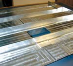
Machining time for this solid titanium part was reduced by 47 percent. See the example below.
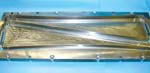
This aluminum part suggestive of a corrugated I-beam was milled out of solid aluminum in less than 3.5 hours. The part was produced by Scott Smith at the University of North Carolina at Charlotte.

This titanium part was created through material addition instead of material removal. Light milling will bring it to its final form.
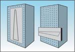
Small flap ribs are positioned near the bottom of the tombstone for stability. For large flap ribs, depth of cut is decreased as the tool rises higher along the vertical axis.
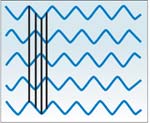
The wavy lines illustrate schematically how a tool with irregularly spaced cutting edges produces an interval between impacts that varies from one edge to the next. When the irregularity breaks up chatter, heavier cuts are possible.


Where consistent depth is critical, corners are a cause for concern. Entering an internal corner causes the radial depth of cut to increase.
The wavy lines illustrate schematically how a tool with irregularly spaced cutting edges produces an interval between impacts that varies from one edge to the next. When the irregularity breaks up chatter, heavier cuts are possible.
Two metals associated with the aerospace industry are aluminum and titanium. One is easy to machine. One isn't.
Over the last several years, milling aluminum at considerably higher metal removal rates has resulted in less expensive aircraft components. The higher speeds and feed rates make it cost-effective to mill complex structures in one piece instead of building them up from smaller pieces. When it's fast enough, machining is less expensive than assembly.


The machined parts are also sometimes lighter. Milling the part complete eliminates the weight of fasteners and in some cases can allow the part to have thinner walls and floors than an assembly would require.
But manufacturers met an obstacle on the way to realizing these benefits. The spindle speed needed to machine aluminum so efficiently can raise chatter to a level where it drastically limits depth of cut. To achieve high metal removal rates through high speed machining, manufacturers had to master this vibration.
Now, these same manufacturers are ready for the next step. Aluminum isn't the only metal from which aerospace components are machined complete. Parts are also machined out of solid titanium. And much of what's been learned about effective aluminum milling at high speeds applies to the challenge of cutting faster in this metal, too.
In fact, the work with titanium takes research into controlling machining vibrations—a topic that has so far focused heavily on aerospace machining—and reveals its significance for the larger world of metalworking. Outside of aerospace, most shops trying to apply the highest machining spindle speeds today are working not with aluminum, but instead with harder metals such as tool steel. The aerospace industry's work with titanium shows the extent to which attention to vibration may be relevant to achieving higher metal removal rates in these harder metals as well.
One site that has begun to apply its expertise with aluminum toward faster milling of titanium is Boeing's military aircraft group facility in St. Louis, Missouri. Boeing associate technical fellow Jerry Halley is an engineering researcher there who has helped the company realize more effective machining of both materials.
"Compared to aluminum, titanium imposes constraints," he says. "Speed is constrained, and heat builds up more quickly. But within those constraints, there's still considerable room for faster cutting."
What Works In Aluminum
The aluminum part pictured at right illustrates what high speed machining makes practical. Measuring 18 by 24 by 2 inches, this part was hogged out of a solid aluminum block in just under 3.5 hours. Controlling vibration—that is, controlling chatter—was essential for two reasons. First, more stable cutting made it possible to combine high speed with high depth of cut to realize the high metal removal rate. Second, controlling vibration allowed the part's thin walls and floors to be machined without deflection. Walls and floors on this part are 0.020 inch thick.
The key to machining a part like this productively is to run at just the right rpm. Chatter results when the steady frequency of the cutter hitting the part interferes with the waves in the surface that the previous pass left behind. The onset of this chatter sharply limits the depth of cut at most speeds . . . but not all speeds. Above about 15,000 rpm, most milling processes feature one or more harmonic "sweet spot" rpm values where the cutting frequency and surface waviness perfectly coincide, making it possible to cut smoothly at a significantly greater depth. These sweet-spot spindle speeds will be different for every particular combination of spindle, toolholder, cutting tool and gage length. However, the sweet spots are repeatable for each of these combinations. Vibration analysis can be used to identify the sweet spots, as can simple test cutting. In aerospace shops committed to high speed aluminum milling at these harmonically stable speeds, shop personnel keep track of ideal spindle speeds for every combination of machine and tooling they routinely put together.
Why This Doesn't Work In Titanium
Mr. Halley says an identical thin-wall part could also be milled out of solid titanium. However, there would be no opportunity to find some ideal rpm value for dramatically deeper cuts. The phenomenon of a distinctly more stable sweet spot generally occurs only at higher milling speeds. At the lower speeds titanium would require, vibration tends to affect the process at all speeds in similar ways. As a result, while mastering vibration remains essential for more productive cutting, the approach to vibration control is different.
That difference can be summarized this way:
In an easy-to-machine material such as aluminum, the goal is to take advantage of vibration by maneuvering the dynamics of the process into a niche where the process works better.
But in an application such as milling from solid titanium where the lower speed limits this maneuver room, the best approach is to minimize vibration and avoid its effects wherever possible.
This approach affects the machining strategy in a fundamental way.
Avoiding Vibration
When milling a part out of solid titanium, it's necessary to divide the process into roughing and finishing.
Machining this way is so fundamental to so many processes that it won't even sound like advice to many shops. However, for aerospace shops used to high speed machining of aluminum, the use of roughing and finishing is not necessarily a given. When the cut is stable and the walls and floors are not extremely thin, the pass used to rough the form can also mill the part to its final dimensions, leaving no need for a follow-up pass at some finer depth to achieve the accuracy required. By contrast, fast machining of titanium calls for a more basic strategy.
Vibration is the reason why. Machining titanium at any significant depth of cut incites vibration in the structure of the machine or setup that can be difficult for most shops to overcome. This is particularly true on a horizontal machining center, where the tombstone is prone to deflect and sway.
This vibration typically occurs at such a low frequency that when high-frequency aluminum milling sets it in motion, generally there is no discernable effect on the part. But in titanium milling where the cutting frequency is much lower, the effects can be pronounced. To minimize these effects while keeping metal removal rate high, generally the best compromise is to rough for high metal removal, then avoid vibration during finishing by keeping cutting forces low.
For the specific case of milling on a tombstone, another way to minimize vibration is to mount the workpiece as low down on the vertical fixture as possible. Rigidity is greater near the tombstone's base. If the work is large enough that it needs the upper part of the tombstone as well, then take progressively lighter depths of cut as the tool rises higher up the face.
All of this advice has to do with working around low-frequency vibrations in the machining system. Higher-frequency vibrations in the same system don't necessarily have to be avoided. These can often be eliminated through a change in cutting tool.
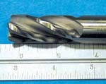
An end mill with irregularly spaced cutting edges breaks up the higher-frequency vibrations. (See photo at left.) This tool design produces both irregular cutter impacts and irregular waviness in the surface, thereby minimizing the chance for these two effects together to establish the steady rhythm that results in chatter. The benefit can be a higher metal removal rate in roughing, where less vibration can mean a larger depth of cut.
Mr. Halley notes that many aerospace shops are familiar with another tool design that also uses irregularity—the "corncob" tool that staggers rows of small cutting edges so the edges strike at varying axial depths. This tool works well for shops performing rough milling in aluminum on lower-speed machines. However, he cautions against using this tool in titanium. One consequence of the staggered tooth design is that the crest of each tooth bears the full brunt of each complete rotation. And in titanium, even at a relatively low feed rate, that's typically too much chip load. The crests of a corncob tool tend to wear quickly in this material.
Aluminum Techniques That Do Apply
Some techniques fundamental to effective aluminum milling at high rpm apply directly to the challenge of faster titanium cutting, Mr. Halley says. These techniques include:- Attention to corners. When a tool making a cut along a straight wall enters an internal corner, radial depth of cut stands to increase significantly. (See illustration.) Particularly at high speed, the resulting increase in load can affect tool life, accuracy and surface quality. One straightforward approach to this problem is to machine the corners first at a slower speed. Getting the material out of the corners makes it safe to run as fast as possible through the straight sections that remain.
- Use of carbide. Faster machining argues for greater use of carbide in titanium just as it does in other metals. High speed steel tooling is generally more economical when speeds are low, and HSS remains the preferred tool material in many titanium applications today. But because of carbide's ability to retain long tool life at high values of sfpm, carbide becomes the more cost-effective choice as cutting speeds increase.
Mr. Halley says there is one technique useful in high speed aluminum milling that often must be entirely abandoned where critical cuts in titanium are concerned. In aluminum, a strategy of high radial immersion combines a large radial depth of cut with a comparatively small axial depth of cut to achieve high stiffness with a high metal removal rate. And while that same stiffness might also be beneficial in titanium, here the price is too high. In titanium, a large radial depth can keep the cutting edge engaged too long, increasing the temperature and concentration of heat. As a result, a strategy of low radial immersion tends to be the better approach. Radial depth of cut is held to no more than 10 percent of cutter diameter. The metal removal rate comes from the axial depth of cut, which can be increased to the point where deflection or vibration sets in.


Related Content

YCM Alliance Hits IMTS
YCM Technology has joined with other like-minded machine tool manufacturers to take a solutions-based approach to manufacturing.
Read More
How to Accelerate Robotic Deburring & Automated Material Removal
Pairing automation with air-driven motors that push cutting tool speeds up to 65,000 RPM with no duty cycle can dramatically improve throughput and improve finishing.
Read MoreRead Next

3 Mistakes That Cause CNC Programs to Fail
Despite enhancements to manufacturing technology, there are still issues today that can cause programs to fail. These failures can cause lost time, scrapped parts, damaged machines and even injured operators.
Read More
The Cut Scene: The Finer Details of Large-Format Machining
Small details and features can have an outsized impact on large parts, such as Barbco’s collapsible utility drill head.
Read More