
Good Parts, Good Measurements
A machine tool must be capable of generating both, says a software company with a new vision for the role of metrology data in the emerging era of globally integrated manufacturing enterprises.


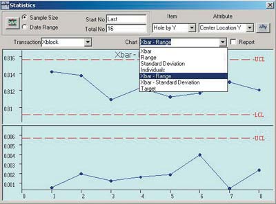
Control of processes is the ultimate aim of part measurement. At the machine tool, an operator can use CAD-based reports such as this target chart playback to monitor the gradual drift in feature location. This information helps the operator understand the process in real time.
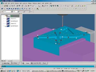
CAD-generated part geometry lends itself to visualization of metrology functions. This 3D image is a display of touch probe motions in XactCNC’s offline programming and editing utility.
A machine tool must be capable of generating both good parts AND good measurements, says a software company with a new vision for the role of metrology data in the emerging era of globally integrated manufacturing enterprises.
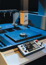
Coordinate measuring machines, such as this Carl Zeiss Prismo, with scanning capability, represent some of the most advanced applications of digital technology in dimensional metrology. Measurement data from such devices promises to play a prominent role in integrating the supply chain.
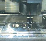
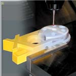
Touch probes on machine tools such as this machining center from Monarch Machine Tool allow parts to be inspected while still in the clamping fixture. Opportunities to take corrective action effectively are best at this point.
EDITOR'S NOTE: In mid-2002, Xygent was purchased and absorbed by Brown & Sharpe. Any inquiries regarding metrology software applications found in this article should be directed to Brown & Sharpe.
In the last 20 years, much has been said about the gap between design and manufacturing. Whereas design is about describing ideal parts, manufacturing is about making real parts.


Digital technology has certainly streamlined, automated, condensed and enhanced both of these disciplines. We have CAD, the digital technology that magnifies our ability to describe ideal parts. The power of 3D solid modeling represents its current peak. We have CAM, the digital technology that magnifies our ability to produce real parts based on CAD-defined geometry. Complex shapes produced on multi-axis CNC machine tools are one manifestation of CAM’s power.
Clearly, CAD/CAM has created a revolution in the design and manufacturing of almost everything we produce in our shops and factories. The tremendous gains in productivity have steadily raised our standard of living. Collectively, our material wealth has never been greater.
Yet the gap between design and manufacturing persists. The reason is simple and inescapable. In a perfect world, the ideal and the real would match perfectly. Unfortunately, we do not live in a perfect world. There is always some difference between the ideal and the real, some difference between the part as designed and the part as manufactured. The theoretical realm of perfect 2D and 3D geometry must yield to the practical conditions of imperfect axis moves, inexact cutter comps and quirky clamping forces.
As parts have become more complex and their function more critical, this inevitable gap between ideal part designs and real manufactured parts becomes more troubling. Quite literally, it threatens our ability to make progress on all fronts, from the exploration of outer space and the cure of deadly diseases to the reliability of household appliances and the affordability of our playthings.
Compounding the situation, our most ambitious and potentially most rewarding projects increasingly rely on collaboration. It takes hundreds of companies working together to design and manufacture a jumbo jet, an orbiting space station, a cell phone or an artificial heart. These companies are likely to be scattered across continents, time zones and cultures. Everything hinges on the supply chain.
Here again, digital technology has had a tremendous influence. We have the Internet, a global communications network making it possible to share digital information virtually unhindered by geographical distance. The Internet can be used to grant nearly universal access to data. We have intranets, network channels that operate within organizations for special purposes and controlled access. Communication across these networks is immediate, even instantaneous.
This access to data via the Internet or intranet revolutionizes the nature of the production supply chain. Digital technology magnifies our ability to collaborate. It intensifies the competitive pressure on companies vying to participate in the chain, for suppliers must be able to serve customers wherever they may be. In this context, the challenges created by the gap between design and manufacturing loom all the more urgently. The world may seem small, but its imperfect nature has not diminished in the least.
So how do we cope?
Metrology To The Rescue
Coping with an imperfect world. Dealing with variation.
That, in a nutshell, is what metrology is all about. Metrology is the art and science of managing the difference between the ideal and the real. In part production, dimensional metrology uses measurements to compare the planned performance of a manufacturing operation with its actual performance. This comparison, however, is only the means, not the end, of metrology. The goal is to make sure that the difference between the ideal and real doesn’t matter, to make sure that each actual part is truly good enough to fulfill its function. Ultimately, metrology achieves this goal not by measuring and comparing, but by using measurements and comparisons to control processes.
In short, metrology is meant to bridge the gap between design and manufacturing.
Because design and manufacturing are driven by digital technology, metrology also must use digital technology to bridge the gap between them. We’re already half way there. Metrology has been moving to digital technology in parallel with the development of CAD and CAM all along. Coordinate measuring machines, for example, began appearing not long after numerically controlled machine tools first moved into shops and plants. Today, almost every type of measurement instrument has an electronic version capable of generating data in a digital format, from plug gages to micrometers to the latest optical or laser-based noncontact measuring machines.
Unfortunately, using this data to close the loop between CAD and CAM and to integrate the supply chain still faces several obstacles. Programming systems for computerized measurement devices often require original part geometry to be translated or reformatted. This step may alter or degrade the inherent precision of the geometry. In some cases involving aerospace parts, for example, the precision lost in translation exceeds allowable tolerances.
Inspection routines created by one programming system may vary significantly from routines created by another. The number of data points collected or the order in which they are collected may vary from system to system.
More important, different systems may use different algorithms to do certain calculations. Two systems calculating roundness or concentricity, for example, may not agree on the results because of the computations used. One system may accept parts that prove not to fit during assembly whereas the other system may reject parts that were in fact usable.
Measurement data may be stored in a database that cannot be accessed by other software applications. Likewise, data may be displayable only in tabular format, making it difficult to detect problem areas.
What is needed is a more powerful way to convey the meaning of measurement data in terms of part geometry. This technology is only now beginning to emerge. It promises to have a profound effect on how manufacturing works. This technology will change how we use inspection equipment on the shop floor. Likewise, this digital technology will change how we use machine tools as production equipment.
One of the companies that is responding to the need for new digital technology in part measurement is Xygent, Inc. (Warwick, Rhode Island). See the sidebar below. This company’s approach to metrology software reflects the trends created by global chains of suppliers acting jointly to speed products to market. Xygent’s software offerings are representative of the direction metrology software is currently taking.
An Architecture For Digital Measurement
As of March 2002, Xygent has released four software products, all based on what the company calls “enterprise-wide metrology architecture.” This architecture was developed to solve some of the problems that have restricted the use of metrology data in the past. Earlier software, including the company’s own products, tended to be based on proprietary systems with widely varying user interfaces and database structures. The company’s new architecture, named XactCOM, is based on Microsoft Corp.’s Component Object Model, a set of software development standards designed to ensure that applications will work together readily in a Windows operating environment. This model specifies how software modules within an application must be structured to interact in a known, predictable fashion. This model also imposes specifications for the rules, or protocols, by which data is created, stored and shared with an application. The Component Object Model specifications are uniform and well documented. Other developers who adhere to this model can create applications that will readily exchange data and share functionality with software modules in XactCOM applications.
Such “openness” makes it more likely that application software from different vendors will be compatible, a boon to users working together with different systems, whether in the same company or on a network. For example, the XactCOM database structure allows data to be accessed through application interfaces written in Visual Basic for Applications (VBA), another widely used Microsoft software development tool. A developer of software for statistical process control can easily create a link that pulls in measurement data generated by a metrology device running an XactCOM-based application.
The architecture also establishes a common graphical user interface for its metrology applications. These applications can all draw from the same set of icons, task bars, menu formats, pop-up selection boxes and so on, giving applications the same look and feel.
Most important, however, this architecture is based on ANSI Y14.5.1—1994. The company claims that this is the first implementation of this standard, which is an extension of the familiar Y14.5 Geometric Dimensioning and Tolerancing (GD&T) standard for defining, describing and annotating tolerances in part designs. ANSI Y14.5.1—1994 goes a step further and establishes a uniform interpretation of the mathematical computations implied by the GD&T standard. In other words, it standardizes what math formulas to use and what procedures to follow for solving metrology computations such as roundness or concentricity.
These formulas and procedures were standardized to yield the most precise results, rather than the fastest computational speed, for example. By implementing this standard in XactCOM, the applications based on it “do the math” in the same way. This means that a CMM, a vision system, or a machine tool touch probe will collect point coordinates in the same order and use the same algorithms to determine alignment, roundness, straightness and so on. Thus the results will be unambiguous and comparable, not reflecting the vagaries of the software used by the various metrology systems.
XactCOM also establishes a uniform approach to relating measurement results to a CAD model. Essentially, it provides a means for interpreting and displaying measurement results as a graphic overlay that can be imposed on a CAD model, creating a “picture” that represents the actual part based on its real-world measurements. This 3D image can be viewed interactively—zoomed, rotated, put into multiple views and so on.
Finally, this architecture includes uniform provisions for coding text and data in the HTML or XML formats. HTML (hypertext markup language) and XML (extensible markup language) are the standard, vendor-neutral codes for tagging digital information for the Web. HTML and XML allow any Web browser to find information in the Internet, identify what type of information it is, and display it in a readable, usable mode on a Web page.
This metrology architecture establishes the framework for the company’s suite of metrology applications. Because other developers of metrology software will have to deal with the same issues, they are likely to move along similar lines in product development.
Xygent reports that it has worked in cooperation with CMM builders such as Carl Zeiss IMT Corp. (Minneapolis, Minnesota) and machine tool builders such as Monarch Machine Tool (Cortland, New York) to develop applications of its architecture. Xygent is promoting XactCOM for adoption as a de facto standard in metrology applications, but how widely it might be adopted is yet to be seen.
Reusing CAD Data
An inside look at Xygent’s suite of applications based on its metrology architecture further reveals the shape digital technology is likely to take in the near term and long term. This software includes products for computerized CMMs (XactMeasure), optical and non-contact systems (XactVision), machine tool touch probes (XactCNC) and hand-held instruments (XactGage). Of these, the package for machine tools is especially interesting because it implies a new paradigm for the machine tool as a metrology device.
These applications are designed to run on a CAD/CAM workstation. Just as the typical CAM package includes applications for milling, turning or wire EDM, these metrology applications are tailored for various measurement functions. The user opens an application after part geometry has been created in CAD, much the way he or she might call up a milling program to generate a tool path for a machining center.
After launching this application, the CAD file representing part geometry can be imported in its native format (direct links exist for the leading CAD systems) and displayed “as is.” The geometry does not need to be translated before the user begins to select part features and apply measurement parameters. The precision of the original geometry is thus retained.
For the programmer, the process of creating the CMM inspection routine is not unlike using a graphical NC programming editor. Tools and planning aids are provided for generating the inspection routine, simulating and verifying it, and developing a strategy for analyzing measurement results. The software appears to be on par with advanced machine tool programming systems. Other inspection tools include a tolerance editor that prevents the user from applying a tolerance not valid for the feature selected, automatic feature recognition to link routines with features quickly, simulation of the inspection program for optimization and verification of the setup, and so on.
The completed inspection program can be downloaded at the CMM. If this machine is also running the same application software, the CMM operator will find the same tools to edit the inspection routine, organize measurement data and display the results graphically. Data can also be transmitted directly to the CAD/CAM workstation and imported to an SPC system or other application.
Machining And Measuring In Parallel
The counterpart of XactMeasure for machine tool touch probes is XactCNC. This software allows the CAD programmer to develop inspection strategies for part inspection on the machine tool. Not unlike CAM software that has off-line as well as shopfloor programming capability, XactCNC also runs on the PC in the CNC unit for online operations at the machine tool. According to developers, this software allows the machine tool to perform in-process inspection routines that allow the operator to monitor and control the machining process in real time to an extent not generally possible.
Using a machine tool to make measurements is not new. Probing systems for machine tools have been around for 2 decades or so. Machine mounted probes have proven to be reliable instruments for collecting data about workpiece dimensions, cutting tool conditions, and machine performance. Renishaw, the leading touch probe developer, has steadily advanced the functionality and performance of touch probes for machine tool applications.
Data collected by the touch probe have many valuable uses. Detecting a broken or missing tool is an obvious example. Checking a workpiece feature so that compensatory machining routines can be calculated to remachine poorly sized or missing features is a more sophisticated application. Inspection routines requiring complex analysis, however, have generally called for removing the part and taking it to a CMM.
The intent of XactCNC is to enable the machine tool to make its own comparison of the actual part and the CAD drawing, and to do so “in parallel” with the machining operations. A CMM can make this comparison but not in parallel with machining operations because the CMM requires the part to be removed from the machine tool. An obvious example: a CMM cannot be used to determine if a part is aligned properly in the clamping fixture on the machine tool. The values for shifting and rotating the part or for adjusting work offsets to compensate can only be determined with the part in the fixture.
Likewise, the machine’s probe can be used to locate a critical surface such as an airfoil on an aerospace part, with the part in its clamping fixture. By linking this surface to the corresponding feature in the CAD model, this surface can be used to zero in on the machine’s axis so that subsequent machining operations will be performed relative to this surface.
Similarly, a rough casting or forging can be probed in its fixture, and the workpiece’s volume can be compared digitally to the net volume of the as-machined shape represented in the CAD model. Workpiece material conditions can be analyzed to determine how the machining program should be oriented to find sufficient stock to yield a good part. An undersized or malformed part that cannot be successfully machined will be rejected before time is wasted in the attempt.
Probing data makes process monitoring more effective when real-time analysis of trends can be accomplished. Touch probes connected to “online” SPC software can track trends to predict machine maintenance or detect operator error such as locking clamps out of sequence. Maintaining stable control over a process allows sampling frequency to be reduced.
Likewise, if a touch probe detects machining errors before a part is removed from the machine, there is a good chance that the part can be remachined to correct the errors. A CMM, of course, could detect the errors, but removing the part from the machine tool to do so would diminish, if not destroy, the opportunity to rework the part. This is especially true of thin-walled or flexible workpieces influenced by clamping pressures. However, the probing data must be analyzed quickly and effectively to determine an effective rework strategy. It may be possible to remachine one feature to create a new datum reference point that brings other features, such as a bolthole circle, into tolerance, rather than rework the entire circle of holes.
Machining and measuring in parallel also means that there are fewer and shorter delays between measuring and reacting. Undesirable trends can be spotted and corrected before out of tolerance parts are produced. Subtle effects of changes in machining parameters also can be detected to optimize a machining process. A grid of touch probing points on a surface may detect a characteristic waviness indicating chatter, calling for feeds and speeds to be reconsidered.
Information About Real Parts
The production supply chain lives by three simple principles: Do it faster. Do it cheaper. Do it better. These three principles judge the value of digital technology as a tool for collaboration. Sharing metrology data allows companies on the supply chain to work with information about real parts. However, this information must be timely, reliable and precise. This kind of information helps companies save time, reduce costs and enhance product appeal.
One of the main enemies of efficiency is guesswork. Guessing slows down production. Guessing adds cost and conceals opportunities to reduce cost. Without precise, reliable information about real parts, guesswork in manufacturing is unavoidable. Will all of the parts being shipped from a supplier in Mexico mate with those from a supplier in Ohio? How much part variation should be allowed for in the design of jigs and fixtures? Can we ease tolerances without compromising fit and function? Similar questions abound.
Many could be answered based on a clear, CAD-based representation of measurement data. With a model of the tolerance band that a group of parts falls within, clamping fixtures could be designed to comply with actual part conditions, for example. Assembly operations could be validated in a virtual environment, and unwelcome surprises could be avoided on the shop floor. The distribution curves for each batch of parts could be studied to be sure they match the distribution of mating parts. Historical data could be used to evaluate suppliers and how well they react to design changes and feedback from the customer’s operations.
Clearly, one of the main allies in the struggle to overcome guesswork is precision, the ability to maintain a tight link between the CAD model and measurement data. The digital technology to deploy this ally appears to be at hand.
New tactical resources must also be developed. Developers at Xygent see several areas emerging as the next opportunities for further progress. We need to improve the capability of machine tools to function as measurement devices, they say. Machine tools must emulate advances in CMM technology. For example, high speed scanning of surfaces to capture a dense point cloud would enhance the evaluation of sculpted surfaces as found in mold, die and aerospace machining. Scanning would give more detail about surface conditions and help detect subtle changes in cutter or machine performance.
We need to develop more robust strategies for validating the inherent precision of machine tools. Today’s machines are more capable as measuring devices than the level of trust in their measurement data would suggest. Myths about machine tool-based metrology must be replaced with science.
We need to forge a closer link between metrology and CAM. Decisions about how best to machine a workpiece should be informed by knowledge of machining results. In other words, there should be a closed loop between measurement data and process plans. Likewise, how best to inspect a workpiece should be informed by knowledge of machining techniques. If the direction of cut affects surface characteristics, and if surface characteristics affect measurement results, this connection must be accounted for, to cite one possibility.
What lies on the horizon, however, should not distract from the urgent business at hand. Companies on every level of the supply chain must promote a new role for metrology as the means to shrink the gap between design and manufacturing.


Related Content

How to Choose the Right Cut Off When Measuring Roughness
Measurement results for surface finishing parameters can vary depending on the filter parameter (Lc), also known as the cutoff.
Read More
Building an Automation Solution From the Ground Up
IMTS 2022 provides visitors the opportunity to meet with product experts to design automation solutions from scratch.
Read More
Determining Out-of-Roundness at the Point of Manufacture
George Schuetz, Mahr Inc.’s Director of Precision Gages, offers these techniques for measuring roundness on the shop floor.
Read More
How to Calibrate Gages and Certify Calibration Programs
Tips for establishing and maintaining a regular gage calibration program.
Read MoreRead Next

3 Mistakes That Cause CNC Programs to Fail
Despite enhancements to manufacturing technology, there are still issues today that can cause programs to fail. These failures can cause lost time, scrapped parts, damaged machines and even injured operators.
Read More
The Cut Scene: The Finer Details of Large-Format Machining
Small details and features can have an outsized impact on large parts, such as Barbco’s collapsible utility drill head.
Read More
