High Speed Machining: Aerospace -- Boeing's One Part Harmony
Faster, lighter cuts can let one solid part replace an assembly of hundreds of components. Better manufacturing and a better airplane both result. But before Boeing could realize these benefits, a more finely tuned process was needed.
.jpg;width=70;height=70;mode=crop;format=webp)


.jpg)
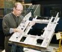
Some within Boeing call this part the "pork chop." Actually, it's a landing gear bulkhead for a C-17 cargo plane. This part used to be assembled from extrusions and sheet metal components, but thanks to high speed machining, it's now produced complete at the machine tool. Total machining time is about 12 hours.

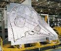
The speed brake pivots up from between the two rudders on an F-15 fighter. High speed machining made it practical for Boeing to mill this part complete out of solid aluminum, instead of assembling it from about 500 smaller components. When assembly was part of the process, the required lead time for one speed brake was about three months. Now, that lead time is measured in days.

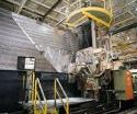
The St. Louis facility currently has three production machines devoted to high speed machining. This horizontal maill is the oldest, but it was made new again through the installation of new drives, a high speed control, and a 20,000 rpm spindle.
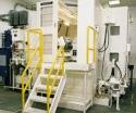
This experimental high speed machine—part of the St. Louis laboratory—features five axes of continuous motion, linear motors in X, Y, and Z, and a 36,000 rpm spindle capable of automatic vibration damping while the machine is in-cut.
Says Boeing's Jerry Halley, "High speed machining is the first new technology to let us machine faster, better and cheaper at the same time, while leaving less weight in the finished part."
Fly an airplane fast enough,and you meet a threshold. Air can't flow out of the way anymore, so all you can do is plow through it. Accomplish this, and you have broken the sound barrier.
Mill an airplane component fast enough, and you also meet a threshold. As spindle speed increases, ultimately it reaches a point where cutting edges are striking the material at a frequency identical to some resonant frequency of the machine. However, this "sweet spot" is no barrier—it's an enabler. Milling in tune with the harmonics of the machine offers a key not only to more effective manufacturing, but also a superior design.


The idea has already seen practical applications. The Boeing F/A-18E/F tactical fighter is easier to manufacture, easier to assemble, even easier to maintain in the field—all thanks in part to high speed machining.
The plane uses 42 percent fewer parts than earlier models in the same family, even though it is also 25 percent larger. High speed machining helped bring about this reduction by allowing large structural components to be machined in one piece, where before they were assembled from many smaller subcomponents (including sheet metal parts and extrusions). Faster spindle speed played an essential role in this transition only because the resulting "monolithic" structures feature thin walls and other delicate features. The faster speed permits faster feed rates, and the faster feed makes it possible to machine these delicate features at light depths of cut without sacrificing metal removal rate.
Few parts illustrate the benefits as well as a component for a similar plane—the speed brake for the F-15 fighter. This is an 11-foot-long moving structure that pivots up from between the two rudders on the completed aircraft. Formerly assembled from 500 separate components, this structure is now milled out in one piece through high speed machining. Light depths of cut are essential, because the part includes numerous thin walls and floors, many as thin as 0.040 inch.
Given the light cuts, the finishing passes alone on one side of this part take around 30 hours. And that's with a high speed machine tool. A conventional speed machine tool could do the same work, but the machining time would stretch to days. There would also be the difficulty of scheduling so much open time on one machine tool. Only high speed machining makes it practical to machine a component like this in one piece.
And "practical" is indeed the operative word. High speed machining changes the lead time and cost-effectiveness of light-depth-of-cut milling. But Boeing principal technical specialist Jerry Halley stresses that high speed machining does not make anything possible that was not possible before.
Says Mr. Halley, "Everything we do on our high speed machines we could also do on slower machines."
In fact, when scheduling is tight on the high speed milling machines at his facility, light-depth-of-cut milling work can be assigned to slower machines. The only loss is in cost and lead time, not in the quality of the finished product.
Mr. Halley works at the same Boeing site in St. Louis, Missouri, where the F/A-18E/F components are machined. For about eight years, he has been studying high speed machining here. The site began as a McDonnell Douglas facility, and much of the development of high speed machining processes now used there occurred before that company was joined with Boeing. For simplicity, however, this article will refer to the site—then and now—as Boeing St. Louis.
At essence, the goal of Mr. Halley's research is to learn how best to take advantage of faster milling spindle speeds. "Light cutting is what makes it possible to consolidate parts," he says, "but you need the speed to make light cuts pay."
Today, the Boeing facility runs its fastest production machining operations at speeds ranging from about 18,000 up to 40,000 rpm. Even so, Mr. Halley prefers not to describe high speed machining in terms of any particular number.
Why then does milling in this range of rpm constitute high speed machining?
Because in this range, he says, only the right rpm number will do. Faster is not necessarily better.
HSM Defined
Pick a number. It can be rpm, sfm, or even the "DN" number (rpm × bore diameter of the main bearing) favored by spindle manufacturers. To Mr. Halley, all of these measures are inappropriate for defining how high speed machining—at least in aluminum—is different from conventional machining. In aluminum, the cutting force available to today's machines and tooling generally doesn't set speed limits. Instead, the limit is set by chatter. That's why Mr. Halley prefers a different definition of high speed machining, one he first heard articulated by Dr. Scott Smith, a researcher at the University of North Carolina at Charlotte.
That definition says high speed machining is machining at or near the resonant frequency of the machine.
Stated another way, high speed machining occurs when you put the chatter to work for you.
To visualize this, think of a car that rattles. Drive faster, and the rattle intensifies.
The same thing happens with chatter in aluminum. Before a high speed milling machine reaches the metal removal rate that its speed and horsepower theoretically enable it to achieve, chatter intensifies to a point where surface finish, accuracy, and/or tool life are all unacceptable.
Now drive that car faster still. The rattle disappears. The noise that was so annoying at 25 mph may vanish at 40 mph—and resonant frequencies explain why. At the faster speed, the engine has found some rpm at which the loose component is vibrating in tune with the system, instead of rattling at odds with it.
And this same phenomenon holds the key to breaking the chatter barrier.
Reducing spindle speed may reduce the chatter, but increasing speed may reduce the chatter, too. The latter occurs if spindle speed can be increased to a point where the machine is vibrating in tune with the frequency at which the tool is striking the material. Here, chatter drops off. Increasing the speed beyond this resonant frequency will again intensify chatter until another sweet spot is found.
The frequencies are repeatable. But even so, finding a machine's resonant frequency one time does not mean the riddle of that machine has been solved. Here's why:
Resonant frequency is a characteristic of more than just the machine tool alone. More accurate would be to say it's a characteristic of the entire machining system, and this system consists of more than just the machine. Changes in the fixturing and tooling can also affect chatter behavior.
Of these two, fixturing is the easier for Boeing St. Louis to keep consistent. Most of the machining done here today involves no fixturing at all. Instead, the aluminum billet itself is bolted to the table, and the part is machined out of it complete except for break-away tabs.
The cutting tool and toolholder are a different matter, however; these are obviously subject to change. And each change creates a new system with its own set of sweet spots.
To deal with this, Boeing St. Louis set about learning in advance what was the right speed for every machining system it would use—that is, every possible combination of machine and tooling.
Perhaps the most radical step the shop took in pursuit of this goal was to limit how many such combinations were available. This step involved cooperation between the separate Programming and Manufacturing groups to an extent that had never been necessary before. Programmers used to decide what cutting tools would be used in a given process, and Manufacturing would implement their decisions. But now, with the cooperation of programmers, Mr. Halley and others at Boeing St. Louis have decided on a standard set of cutting tools for high speed machining. (See "Disciplined Tooling.")
The effect of standardization was to limit the number of tools likely to be used in this process to a manageable number. For these tools, Boeing St. Louis then experimented to determine the optimal cutting conditions for every machine and tool combination. These conditions included spindle speed and maximum depth of cut at that speed to avoid excessive chatter. Now, the fruits of these experiments are stored on a password-protected intranet site where programmers throughout the company can retrieve the data for programs intended for the St. Louis facility. Programmers opting for high speed machining now find their selection of tools not from suppliers' catalogs, but from this site. And once they have made a selection from this site, and chosen a machine, the optimal spindle speed and depth of cut for high speed machining are already determined.
All of this assumes, however, that the machine's contribution to the resonant characteristics won't change between the time the sweet spots are measured and the time they are put to use. This may not be a valid assumption. After a crash, for example, the frequency response of the stricken spindle has to be re-measured. And unless the spindle supplier understands the process, then a new spindle replacing a worn-out one may also merit re-testing. This latter case was demonstrated after one of the plant's more recent spindle changes. Changing the spindle had never affected the process so much before, but suddenly all of the predetermined resonant speeds were no longer correct. Only after quizzing the spindle supplier did the company find the reason. The supplier had not thought it important to alert the plant that this was an improved version of the old spindle, with the drawbar design slightly changed.
"Consistency," Mr. Halley stresses. "That's the key to high speed machining."
For now, finding the optimal combination of speed and depth of cut consists of comparing how well the machine performs at maximum speed versus how well it performs when speed is scaled down to the fastest resonant frequency. (See "Find The Sweet Spot.") Usually, the resonant frequency wins. However, Boeing's next goal is to learn to manipulate the resonant characteristics—perhaps through features of the spindle, perhaps through the choice of cutting tool—so that a sweet spot falls exactly at the maximum spindle speed.
In other words, in the near future, the optimal speed may no longer be a consequence of the choice of tool. Instead, the tool would be chosen to take advantage of all the speed the spindle had to offer.
One interesting implication of this plan is that it stands to undermine a high speed machining axiom—the notion that faster machining calls for more rigid tooling.
Once the goal becomes to affect the resonant characteristics, the right tool for a given cut might instead be one that is less rigid.
Imagine, for example, a combination of machine and cutting tool that produces resonance at 38,000 rpm, though the spindle is capable of 40,000 rpm. To change this system so that resonance falls at precisely 40,000 rpm instead, is a more rigid tool or a less rigid tool the answer? It could be either one, depending on the peculiarities of the system. In aluminum, speed does not depend on the tooling so much as the chatter. And to get precisely the chatter characteristics desired, it may be advisable to switch to a floppier tool!
The Ascent
Exactly how Boeing St. Louis will get to the point where it can engineer resonant frequencies instead of accepting them as they are is not yet clear. Mr. Halley believes it may involve specifying frequency response characteristics from spindle suppliers. Whatever the answer, taking advantage of the spindle speed that remains unharnessed is the goal of the high speed machining research continuing today.
In fact, this has been the goal of this research from the beginning. All of this facility's progress with high speed machining has been built on a foundation of research and testing. Today, Boeing St. Louis has a laboratory devoted to high speed machining study. The centerpiece of the lab is a research machine featuring five axes of continuous motion, linear motors in X, Y, and Z capable of just under 2 G acceleration, and a custom-designed 36,000 rpm spindle featuring a system for actively damping vibration while in the cut. The machine was built by the Ingersoll Milling Machine Company (Rockford, Illinois) and funded in part though a federal grant from the Defense Advanced Research Projects Agency.
Compare this machine to what the shop had available when high speed machining research began here about eight years ago. Back then, Mr. Halley used the facility's first high speed machining test machine, a conventional C-frame vertical retrofitted with a Fischer (New Brighton, Minnesota) 24,000 rpm spindle.
This was the machine used to produce the first workpiece Mr. Halley used to illustrate high speed machining's promise. The part was a solid aluminum structure that represented a replacement for a component then being produced as an assembly of five subcomponents. The solid aluminum version had wall thicknesses of 0.030 inch and was machined from billet in 45 minutes without deflecting any of these walls. Mr. Halley produced copies of the part to give to numerous design engineers. Also helping in the show-and-tell effort was a subsequent, more challenging part featuring a 0.020-inch thick floor milled to include 0.080-inch thick unsupported bosses.
"With these parts, we were able to show designers how the techniques we were developing had implications for their own work," Mr. Halley says. "High speed machining was never about taking the old cuts faster. Instead, here was a new manufacturing technique, and an expanded range of options for designers."
And as it happened, the timing was just right.
In the aircraft industry, new manufacturing processes rarely see immediate application. New products—that is, new planes—don't come along very frequently, and simple cost-effectiveness favors sticking with one design for an aircraft throughout its long manufacturing life, even when evolving technology make design improvements possible along the way.
However, Mr. Halley began discussing high speed machining with designers just as the F/A-18 class of fighter was set to see a major redesign. And because of this, his findings saw practical application far sooner than he would have expected. High speed machining became an important factor in reducing the part count and assembly work in the latest version of this plane.
Since then, the shop has ramped up three production machines for high speed machining:
- An Okuma (Charlotte, North Carolina) horizontal machining center with a 24,000 rpm spindle supplied by Ibag (North Haven, Connecticut). This machine is less versatile than the other two, only because its travels (49 inches in X, less in other axes) rule out many of the large workpieces that make the best candidates for this process.
- An older, upgraded horizontal milling machine with 60 feet of X-axis travel. The machine was equipped with new drives and CNC, and a Pope (Haverhill, Massachusetts) 20,000 rpm spindle (now manufactured by SETCO Precision Spindles).
- An Ingersoll "High Velocity" machining center with 40 feet of X-axis travel. The shop's fastest high speed machine, this one has a 40,000 rpm spindle. And like the research machine, it also has linear motor axes. Linear motor accuracy and acceleration are unaffected by the length of travel (not the case with ballscrews), so this technology offers an effective way to bring high feed rate and acceleration to the longest workpieces. This machine is capable of 1,200 ipm feed rate and 0.5 G acceleration.
Already, these machines are no longer enough to handle the plant's high speed machining work load. Even now, some high speed machining work—that is, work that calls for light cuts—is performed using far less efficient milling cycles on lower speed machines. And in the future, demand will only increase as high speed machining is applied to more new products and redesigns. So in anticipation of this demand, the plant is adding more high speed capacity—a lot more.
Today's high speed machines are housed in the existing, long-standing machining area where machines of various speeds and capabilities are located. However, adjacent to that building is another that was built with high speed machining in mind. That building will soon receive the St. Louis facility's most powerful high speed milling machine to date—one that will more than double high speed machining capacity. Called the High Velocity Profiler, this horizontal machine (also from Ingersoll) features two carriages of two spindles apiece. Each of the four spindles delivers 20,000 rpm and 100 hp, and supports the rotating elements on hydraulic fluid bearings (as opposed to ball bearings) for longer life. Spindle heads pivot in two axes to deliver full five-axis machining. X-axis travel is 394 inches. Linear motors deliver 0.3 G acceleration and 1,180 ipm feed rate. And all four spindles together are supported by an automated eight-pallet system. In effect, this building will contain a flexible manufacturing cell for high speed machining of the largest workpieces.
More Chip Making
In fact, Boeing's need for so much more high speed machining capacity reveals something important about the nature and promise of this process. Again, it's not just a way to produce the old parts faster. If it were, there would be no need to add capacity—all the old work would just move through the shop in less time.
Instead, high speed machining offers a way to machine parts that were never practical to machine before. And as a result of machined structures replacing numerous subcomponents—some of them machined parts, many of them not—high speed machining lets CNC milling take on a larger role in the manufacturing process than ever before.
The reallocation of resources represented by the High Velocity Profiler reflects this. Boeing is shifting more resources into machining because it is saving on the resources it must apply to sheet metal fabrication and assembly.
And it's more than an even trade. Replacing multiple stops—machining, fabrication, and assembly—with just one stop for machining saves cost in several ways. For example:
- There is the compressed production time. The one-stop process is invariably faster, and this contributes to a more flexible production process. For example, when the F-15 speed brake was assembled from 500 parts instead of being machined in one piece, it took three months to produce each part. Now, it is possible to machine the part complete in under two weeks.
- There are also the inventory savings. It's no longer necessary to store, track, transport, and (in some cases) lose or damage subcomponents awaiting assembly.
- And there are the overhead savings. Assembly is a floorspace-intensive process, and real estate isn't cheap.
But these are just the manufacturing savings. There is also the fact that high speed machining can produce a better aircraft. Reducing the number of parts in a plane makes that plane less expensive to service in the field. And service—particularly field service—determines the true cost of a military aircraft, not its sticker price. In addition, replacing assemblies with machined parts eliminates fasteners, and therefore reduces the amount of metal needed. Across the entire aircraft, the weight reduction translates into capacity for more fuel and/or more weapons.
Says Mr. Halley, "High speed machining is the first new technology to come along to give us all of this at the same time: faster, better, cheaper, and lighter weight."
Reduced machining forces make it all possible. And according to Mr. Halley, getting to reduced force is simpler than many practitioners of high speed machining say it is. Practically speaking, it only comes from the lighter depths of cut, he says. In his experiments, he has investigated the idea that the speed alone in high speed machining reduces cutting forces—that is, that high speed machining can reduce the amount of work required to remove a given volume of material. He has investigated the idea, but his experiments tend to discount it. At best, he detected only slight examples of this phenomenon, he says—not nearly enough force reduction for this effect to justify high speed machining in and of itself.
In other words, high speed machining produces no magic, he says. High spindle speed is a requirement for high speed machining, but only because it offers a practical way to take light cuts.
Even so, it takes more than just a fast spindle to get to high speed machining.
HSM Prerequisites
The technology permitting spindle speeds of 20,000 rpm or better has been available for some time. But there are reasons why the St. Louis facility began to machine effectively in this range fewer than ten years ago. A fast spindle is the first requirement for high speed machining, but a variety of enabling factors had to come together in order for the plant to put this speed to work effectively.
Some of these factors were cultural. Only improved communication between design and manufacturing departments could have led to the product improvements high speed machining makes possible, as well as permitted the tooling discipline the process requires.
However, many of the enabling factors were technological. Several technology developments helped bring about this process. These include:
- Fast controls. Only recently have CNCs acquired the processing speed to control machine tool motion at high feed rates without data starvation. In fact, in the realm of five-axis high speed machining, Mr. Halley says processing time still imposes a feed rate limitation. Because of the additional data required for the fourth and fifth axes, the CNC cannot deliver motion commands as quickly as the machine can execute them in the most detailed regions.
- CNC tool grinding. The repeatability of the tool grinding process is key because slight variations in the cutting tool can have enormous significance at high speeds. In fact, to safeguard tool consistency even further, the Boeing plant sticks with just one cutting tool supplier.
- Material improvements. Billet aluminum is now consistent enough to be machined into large, delicate structures. Unrelieved stressed that once might have affected geometric accuracy have now effectively been eliminated in high-quality stock. Other problems have also been addressed. Porosity, for example, used to limit aluminum plate to a maximum thickness of about four inches. But now it's possible to machine delicate parts starting with raw stock much thicker than this. The speed brake part, which starts with 6.75-inch thick stock, is one beneficiary of the improvement.
The Model Process
As spindle speeds continue to improve and enabling technologies continue to advance, where will the evolution lead? It seems likely that more speed will make it possible not only to consolidate still more assembled parts into machined structures, but also to coordinate related parts for even better manufacturing flexibility.
Larry Clark is general foreman for the Boeing St. Louis plant. He describes one vision for how high speed machining will affect aircraft production. He notes that the ability to produce parts more quickly, and all in one place, has already led to large left- and right-hand parts being machined from a common billet.
He says this is a trend to watch. If the machine is big enough and can machine each component fast enough, then why not machine all of the structural components at once, from the same piece of aluminum? This would permit true just-in-time delivery to final assembly, because every needed component would arrive at the same time.
Once this occurs, says Mr. Clark, the assembly process would come to resemble one he first experienced decades ago.
"You would separate all the components from the tabs," he says. "Just like I did with model airplanes as a kid."


Related Content

YCM Alliance Hits IMTS
YCM Technology has joined with other like-minded machine tool manufacturers to take a solutions-based approach to manufacturing.
Read More
How to Accelerate Robotic Deburring & Automated Material Removal
Pairing automation with air-driven motors that push cutting tool speeds up to 65,000 RPM with no duty cycle can dramatically improve throughput and improve finishing.
Read MoreRead Next


3 Mistakes That Cause CNC Programs to Fail
Despite enhancements to manufacturing technology, there are still issues today that can cause programs to fail. These failures can cause lost time, scrapped parts, damaged machines and even injured operators.
Read More
The Cut Scene: The Finer Details of Large-Format Machining
Small details and features can have an outsized impact on large parts, such as Barbco’s collapsible utility drill head.
Read More