How To Machine Aircraft Titanium: Getting The Metal Out
Part of a series of articles on machining pockets in titanium parts, this article describes various options for roughing the hard metal efficiently.
.jpg;width=70;height=70;mode=crop;format=webp)
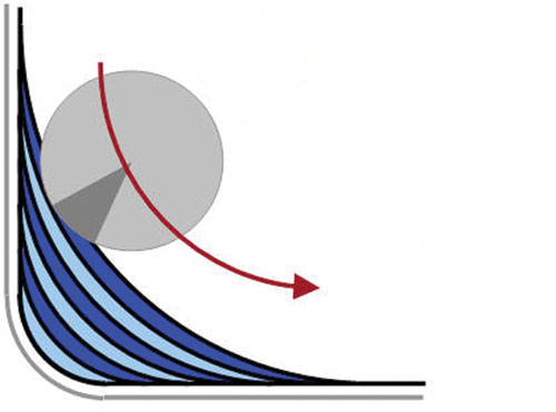
Material can be roughed out of the corner of a pocket by “slicing”—that is, by taking a series of successively shorter passes with a small-diameter tool.
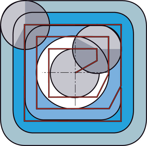
Much of the cornering in this drawing is unnecessary. There is no need for tool paths to conform to the pocket’s shape until the tool actually reaches the walls. See next photo....
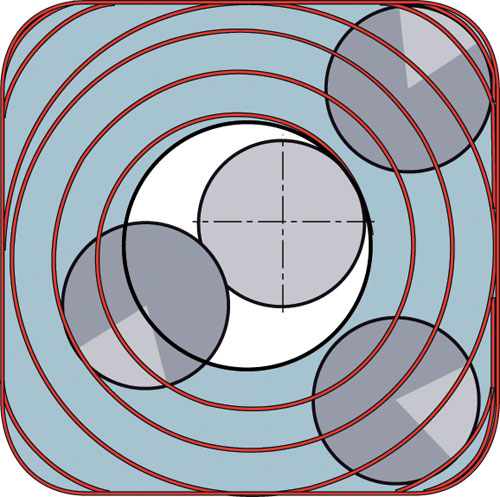
Machining in circles, as illustrated by this drawing, keeps the load on the tool constant.
A relatively heavy amount of stock should be left on the floor of the pocket and machined away in a tool path that spirals out from the center. That way, the area of the floor being machined is always supported by uncut stock left alongside the cut.


The article at right about the 8-to-1 rule describes using end mills with many flutes to take fast finishing passes in titanium pockets. But what about roughing the titanium? If the component is machined from a solid block, then all of the rough stock has to be hogged from the pocket before the 8-to-1 technique can be applied.
Cutting tool supplier Sandvik Coromant has a research group devoted to aerospace machining. This group has worked to develop and evaluate techniques for efficiently machining titanium aerostructure components. Bruce Carter, aerospace projects manager with the company, says when it comes to roughing, there are essentially three options for hogging material out of a titanium pocket. They are: (1) drilling and profile milling, (2) ramping to incremental depths, and (3) drilling and plunge milling.
The first of these is generally the most productive choice, he says. The other two address the challenges of more difficult pockets.
Drill And Profile Mill
This approach begins with drilling a large-diameter starter hole in the pocket. For chip clearance, the drilled hole should be as large as possible, and at minimum, 1.3 or 1.4 times the diameter of the milling tool that will rough out the rest of the area. The rough milling cutter should then reach not quite as deep as the drilled hole—leaving about 0.20 inch of stock in place for finishing the floor later (more on this below). Starting in the drilled hole, the milling cutter proceeds outward to mill the pocket depth in one set of passes. Video animation under Editor Picks at right shows the best way for the milling cutter to enter the material from out of the hole.
This approach represents the most productive material-removal process for pockets in titanium, Mr. Carter says. However, it requires a relatively simple pocket shape that is free of any contour or features that would necessitate changing tools or machining successive layers in certain parts of the pocket. This approach also requires a stable process, meaning the pocket should be relatively shallow, and the tool overhang should be no greater than 4 times diameter. When the pocket is not shallow, or when the process lacks stiffness for other reasons, one of the other two options may be more effective.
Ramp And Interpolate
This approach does not require a drilled hole. It uses just one tool. This is a milling cutter that ramps into the material and interpolates to machine one layer of the pocket before ramping to the next layer. Depths of cut are light, which may make this technique best for less-rigid machines such as some 40-taper machine tools. The technique can be used with a high-feed mill, but a milling cutter with circular inserts can ramp more aggressively.
The approach can be much more effective than the previous technique for pockets that have varying depths resulting from a contoured shape.
Drill And Plunge
This technique is a problem solver, Mr. Carter says. Just like the first technique, this one begins with a drilled hole. However, from there, the machine essentially keeps on drilling—making overlapping plunges with a plunge-milling tool or a drill capable of machining this way. The Z axis is generally the stiffest axis of any machining center, so this technique can allow pockets to be machined in titanium even on machines with poor rigidity. It also offers an excellent way to machine deep pockets requiring tool overhangs of 4 times diameter or more.
Of course, one drawback of this machining technique is the cusps that are left between plunging passes all along the outline of the pocket. These have to be removed in a separate operation.
Corner Concerns
The first two techniques—drill and profile mill, and ramp and interpolate—share a common problem in the corners. Making a right-angle turn to machine an internal corner produces a dramatic increase in radial depth of cut. This can lead to excessive tool wear, tool breakage or unacceptable chatter marks in the corners—not to mention an unpredictable process that is difficult to leave unattended. Therefore, the solution Mr. Carter recommends is to have almost no corners at all. Specifically, instead of milling parallel to the walls of the pocket, he says to mill outward in circles until the walls of the pocket actually do have to be machined in straight lines.
A drawing at right illustrates this. The constant-arc tool paths allow the process to maximize both chip load and radial depth of cut because the load on the tool remains steady throughout this spiraling path. The feed rate may change to allow for more abrupt changes in the toolpath direction as the cutter reaches the wall—but even here, the tool should make large-diameter arcs that steer well clear of the internal corners.
How, then, should the remaining rough stock in the corners be removed? Mr. Carter suggests a technique that Sandvik Coromant calls “slicing”—which also could apply to the material left over in the corners after any of the three pocketing techniques described above.
Slicing
Slicing is a semi-finishing technique in which material is removed from corners via a series of increasingly shorter arcs to get down to a smaller corner radius. Another drawing at right illustrates this.
As the drawing shows, each arc permits a light radial depth of cut. The light pass can be taken at a relatively high feed rate. However, the radial depth increases as the tool gets closer to the corner, so the feed rate should decrease accordingly.
In the end, this leaves a corner radius that is slightly larger than the tool. This is not an approach to finishing corners; plunge and sweep is a technique for that (see the article at right).
The slicing technique applies not only to right-angle corners, but also to corners that are much more acute. Acute corners simply require more slicing passes to sweep out the extra stock that the roughing left behind.
The Floor
The final important consideration for getting material out of the pocket is the floor, which (unlike
the pocket’s walls) might be milled to its finish dimensions. However, finishing the floor involves more stock removal then many shops are used to considering as part of a finish pass.
Mr. Carter says leaving 0.20 to 0.25 inch on the floor of the pocket is good practice in milling a titanium aircraft component. This amount of stock helps support the thin floor against vibration as the material is machined away.
To ensure a stable cut, the floor of the pocket is machined to its finished depth in rings radiating out from the drilled hole. Thus, the cut always has unmachined stock next to it to provide support—all the way out to where the support comes from the adjacent walls, which themselves will later be finished, probably using the 8-to-1 rule described previously.
Editor’s note: You can read other parts in this series by clicking on Read Next (to the right).


Related Content

Threading On A Lathe
The right choices in tooling and technique can optimize the thread turning process.
Read More
Toolpath Improves Chip Management for Swiss-Type Lathes
This simple change to a Swiss-type turning machine’s toolpath can dramatically improve its ability to manage chips.
Read More
Best Practices: Machining Difficult Materials
Cutting hardened steel, titanium and other difficult materials requires picking the right tools, eliminating spindle runout and relying on best practices to achieve tight part tolerances.
Read More
All-Around Mill Improves Productivity and Cost for Valve Job
Adopting a mill with a double-negative rake and pockets compatible with multiple insert geometries enabled Progressive Metal Service to increase feed and lower scrap rates for a valve.
Read MoreRead Next

How To Machine Aircraft Titanium: Plunge And Sweep For Finishing Corners
Part of a series of articles on more efficient machining of pockets in titanium parts, this article describes an effective approach to finishing internal corners.
Read More
How To Machine Aircraft Titanium (Introduction To A Series)
Choose cutters, depths and tool paths with attention to particular steps in the process, and you can machine titanium more efficiently than you might suspect. Boeing offers practical tips.
Read More
How To Machine Aircraft Titanium: Pricing The Process Instead Of The Tool
Part of a series of articles on more efficient machining of pockets in titanium parts, this article describes the importance of considering all of the costs that are affected by the choice of cutting tool.
Read More