Impressive Developments For U.S. Gear Maker
This gear manufacturer employs cutting edge technology to help keep customers buying in the United States.


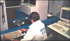
Thomas Mifflin, Arrow gear engineer, uses the Gleason software to develop a bevel gear. The Gleason system produces gear sets that are right the first time, saving the customer as much as 12 months of trial-and-error work that characterizes gear development by the traditional method.
.jpg)
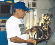
This is a close-up of the machining area of the spiral bevel gear grinder shown below. A formed grinding wheel is seen at left.
This CNC gear inspection machine measures the machined gear tooth geometry, compares it to what it should be and automatically sends corrective instructions to the CNC cutter or grinder.
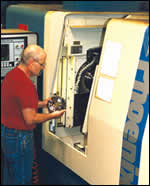
This CNC bevel gear grinding machine automatically sets itself for the job based on gear design data developed on and downloaded from a workstation in the firm's engineering department.
The machining summary is automatically downloaded to this CNC bevel gear cutter, reducing setup time for the machine to about 1 hour compared to 4 to 6 hours for a conventional bevel gear cutter.
For the last 10 years or more, Arrow Gear Co. (Downers Grove, Illinois), an aircraft/aerospace gear manufacturer, has seen a significant amount of business go offshore as customers chased lower prices for gearsets in countries with lower wages. Then came 9/11, which depressed air travel in the United States, resulting in severe cutbacks in aircraft building programs. Arrow was seriously affected. The company claims to manufacture more gears for jet engines than any other company in the world, and it lost $6 million in sales for one project alone when the build schedule for the 737 was reduced from 28 planes per month to 14.
Arrow is confident that the air travel industry will eventually come back, but the company needed a strategy for survival until then—one that would reduce and perhaps even reverse the loss of business abroad. The company has always tried to stay on the cutting edge of technology to stay competitive, and it again turned to the latest technology for the solution to its problem. Specifically, the firm implemented a new system that dramatically reduces the time and cost for the development and manufacture of spiral bevel gears used for various jet engine applications. (In the gear industry, the term development refers to designing the tooth profiles of mating gears in such a way that operating loads continue to be efficiently transmitted regardless of possible changes in operating conditions.) Arrow’s new system employs a Phoenix CNC spiral bevel gear cutting machine, three Phoenix CNC spiral bevel gear grinding machines, and a family of spiral bevel gear development, analysis, machining and inspection programs, all from Gleason Corp..


Appreciating the significance of Arrow’s new system requires some understanding of the way spiral bevel gears are typically designed and manufactured. To begin with, the contact pattern, or the areas of the tooth surfaces that come into contact as the gear teeth engage and disengage during their rotation, is critical to the performance and operating life of the gear set. If the contact pattern is too small, the gear may not be able to withstand the forces transmitted when the gear set is operating under load. If the pattern is not contained completely within the perimeter of the gear tooth—if it runs off the tip or into the heel of the tooth—the result can be premature failure. To complicate matters, the gears, bearings and other components of the gearbox move as they react to the transmitted loads, temperatures, and other operating conditions, resulting in changes in the gear tooth contact pattern that must be identified and provided for. An ideal tooth contact pattern under load should encompass the bulk of the tooth surface yet avoid any contact with the edges.
Typically, an acceptable contact pattern is arrived at by an iterative process that is used by most gear producers. First, based on previous experience, an engineer will make an educated guess at the gear tooth geometry required to provide a correct contact pattern. Next, the part is fabricated and the gear teeth are machined to an undeveloped summary.
When the gear and its mating pinion are finished, their teeth are coated with a marking compound, and they are run together in a tester. The area of contact can be seen in the disruption of the marking compound. An experienced inspector is required to interpret the visual results.
More often than not, the contact pattern resulting from the initial attempt is unacceptable. Consequently, the settings on the gear tooth grinder are adjusted and a new pinion is ground. The parts are checked again. This trial and error process can continue through many cycles until the best educated guess for contact pattern is achieved.
The next step is to analyze how loading affects the contact pattern. First the gears are mounted in the gearbox and run under light load to determine the contact pattern movement. Then the gears are visually inspected to check the contact pattern, which is indicated by a light wear pattern on the mating tooth surfaces. If the pattern is not correct, which is commonly the case, the gear tooth grinder has to be set up again and another pinion ground using slightly different settings. This cycle continues until a suitable contact pattern is developed when run under full load.
“The process of return, regrind, test, return, regrind, test . . . would go on for 4 to 6 months before the customer had a product ready for life testing,” explains Joseph L. Arvin, Arrow Gear’s president. “Typically, millions of dollars are tied up in the design and production of a new jet engine, and the longer that the trial-and-error process drags on, the longer it takes the engine builder to deliver the product to the customer and get paid.”
As Arrow explored ways to increase sales by increasing the services it offered its customers, it started thinking of ways to make the gear-development and manufacturing process faster and less costly for its customers. As part of its ongoing investment in modern gear-making technology, Arrow purchased a Phoenix CNC gear cutting machine and a Phoenix CNC gear grinder from Gleason in the early ’90s. (It has three such grinders today.) In the mid ’90s, the company purchased a Computer Aided Gear Engineering (CAGE) software program from Gleason that produces the spiral bevel gear and pinion tooth geometry for cutting and grinding. Included in the software is Tooth Contact Analysis (TCA) software, which enables the user to establish the optimum contact pattern for a gear set in about one week, avoiding all of the problems with the trial-and-error method described earlier.
Also included in the CAGE software is the ability to download machining instructions directly to the bevel gear cutting and grinding machines and to a Hofler CNC gear-inspection machine.
Two years ago, Arrow acquired Finite Element Analysis (FEA) software, also from Gleason, a gear analysis tool that allows the company to perform advanced simulation of gear designs under load and other conditions using data from the CAGE software. The FEA software completed a closed-loop system that enables Arrow to develop the optimum gear contact pattern for a given application, download the geometry to the CNC cutter and CNC grinder, and machine the gear and pinion right the first time. The geometry is also downloaded to a Hofler gear-measuring machine, which compares the geometry of machined components to the nominal geometry. Any deviations are detected, and corrections are automatically sent to the appropriate machine.
The hub of the closed-loop system is an off-line work station controlled by Arrow gear engineer Thomas C. Mifflin. Working at a PC, Mr. Mifflin begins the process by using the Gleason software to develop the desired spiral bevel gear and create a summary (a set of machining instructions). He then downloads the summary to the Gleason bevel gear cutter or grinder and to the CMM gear inspection machine.
“There are 27 different settings that must be made on a mechanical spiral bevel gear cutting machine, and it can take 4 to 6 hours to set up the machine and take the first cut,” Mr. Mifflin explains. “By contrast, a data file is downloaded to the control of the Phoenix machine, and the appropriate settings for the gear to be processed are automatically made to the machine within 30 seconds. Another hour or so is spent loading the workholding fixture, the gear blank and cutter, zeroing them and then pushing the button to start the machine.
“Similarly, a mechanical spiral bevel gear grinding machine takes 10 to 12 hours to set up and get ready for the first grind,” Mr. Mifflin continues. “With the Phoenix CNC grinder, it takes merely seconds to download the file from the work station to the machine and for the machine settings to automatically adjust to the new job. It might take another 90 minutes to load the appropriate workholding fixture and machined gear and to load and dress the grinding wheel to get ready for the first grind.
“The data file is also downloaded to a CMM gear inspection machine,” Mr. Mifflin continues. “After the gear is cut it goes to the inspection machine, which measures the gear tooth’s flank form. The inspection machine then compares the measured flank form to the theoretical or digitized master, identifies any discrepancies, calculates what adjustments must be made in the Phoenix machine to compensate for the variations, and communicates those changes to the Phoenix machine. The Phoenix machine adjusts to the new settings so that when the operator reloads the part it is ready to recut it to the correct form.
“So far, we’re batting a thousand with the Gleason system,” Mr. Mifflin reports. “Every set of gears that we’ve made using the process has been right the first time. When our customer performs the preliminary tests for qualifying the gear we supplied, he finds that the contact pattern meets all of his requirements. Before, it could take 6 to 12 months of making changes and re-testing to reach this point. In effect, we’ve saved all of that time for the customer, allowing him to go directly into life testing of the gearbox. That time savings translates to a significant dollar cost savings for the customer.”
$250,000 Savings Per Gearset
Not too long ago, Arrow Gear focused exclusively on the manufacturing side of the business and was content to let others do the gear development work. Today, the company regards development work as a stepping stone to prototype and master work and, hopefully, production work. “We don’t want our customers to go offshore for the development of their gears,” Mr. Arvin emphasizes. “We’re confident that, with our state-of-the-art development capabilities, we can save customers about $250,000 per gearset. And once they discover the quality of our spiral bevel gears and our fast turnaround time, we’re betting that we’ll get more production work as well.”
Free Development Service
If the time and dollar cost savings aren’t reason enough for customers to place their gear development work with Arrow, the firm offers still another incentive: There is no charge for the development work as long as the customer agrees to place the prototype and master gear work with the company. Customers who wish to avail themselves of Arrow’s gear development capabilities but plan to have all of the gear manufacturing done off-shore must pay for the service. “We’re not an engineering company,” Mr. Arvin stresses. “We’re in business to make gears, and that’s what we want to do.”
Arrow’s gear development system has helped make them the “go-to guys” for spiral bevel gear design. Engine manufacturers are coming to the firm because of its design capabilities, and it is involved in all or most of the new jet engine projects. Arrow has been calling on aerospace companies that are not currently customers to tell them about its new gear-development capabilities. It has had “great success” with two such companies and a third is “looking at us hard.” Still another company with a captive gear-manufacturing facility is considering having Arrow do its development work in order to save the time and money and be able to get into production faster on new projects.
The firm is also attracting new commercial business. For example, it has worked on a design for a rear axle assembly for a NASCAR race car and has also done some work for Indy cars.
Arrow’s gear development and manufacturing capabilities have also enabled the firm to attract business from overseas aircraft/aerospace firms, reflecting the increasingly international character of the industry. “Until 1989, we had no overseas business,” Mr. Arvin recalls. “Today, one third of our business is exports, which is unheard of for a U.S. gear company. Because of the economy and 9/11, business is down across the board, but our situation would be much worse if we weren’t competing in the global market.”


Related Content

Beyond the Machines: How Quality Control Software Is Automating Measurement & Inspection
A high-precision shop producing medical and aerospace parts was about to lose its quality management system. When it found a replacement, it also found a partner that helped the shop bring a new level of automation to its inspection process.
Read More
SolidCAM Wants to Help Machine Shops Get into Additive Manufacturing
SolidCAM's partnership with Desktop Metal is aimed at making additive manufacturing more accessible to job shops and other manufacturers.
Read More
Modern Bar Feeds Bring New Life to Automatic Swiss Lathes
Cam-actuated Swiss lathes are still the fastest way to process many parts. By adding modern bar feeders, this shop has dramatically improved their utilization with the ability to work unattended, even in a lights-out environment.
Read More
The Strategic Value of Machine Tool Flexibility
This aerospace and defense supplier has a strategy to take advantage of the flexibility in its newest and largest five-axis gantry-type machining center.
Read MoreRead Next

Getting In Gear With An Automated Cell
This production cell embodies several unusual but very effective concepts for keeping process variables under control with little operator intervention.
Read More

3 Mistakes That Cause CNC Programs to Fail
Despite enhancements to manufacturing technology, there are still issues today that can cause programs to fail. These failures can cause lost time, scrapped parts, damaged machines and even injured operators.
Read More