
Internal Grind Machines: Maintaining Components’ Alignment
This article outlines the importance of this alignment, explains how to recognize the symptoms of misalignment and describes what corrective steps to take. The author, Bill Bednarski, is an applications engineer at Saint-Gobain Abrasives in Worcester, Massachusetts.
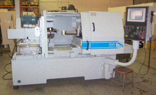
Figure 1a
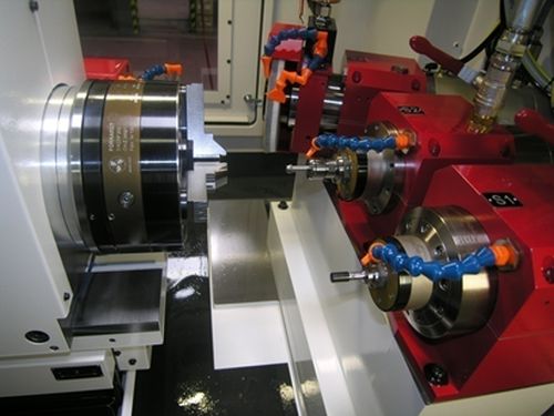
Figure 1b
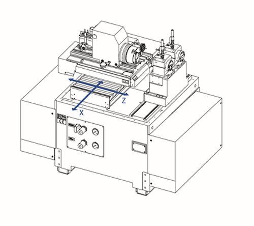
Figure 2a
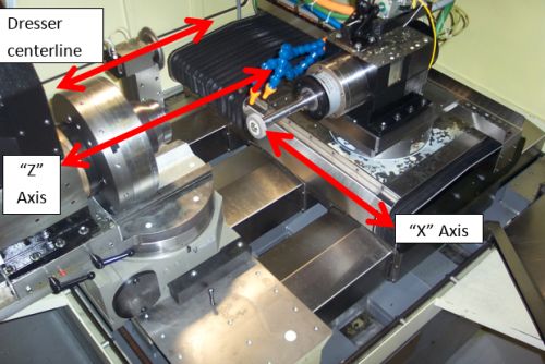
Figure 2b
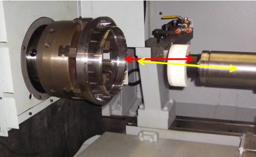
Figure 3
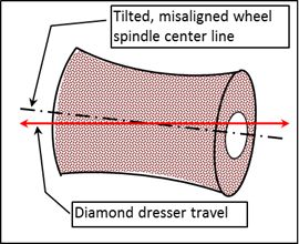
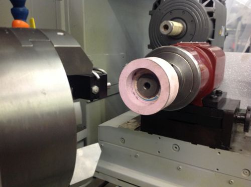
Figure 4a
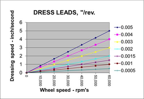
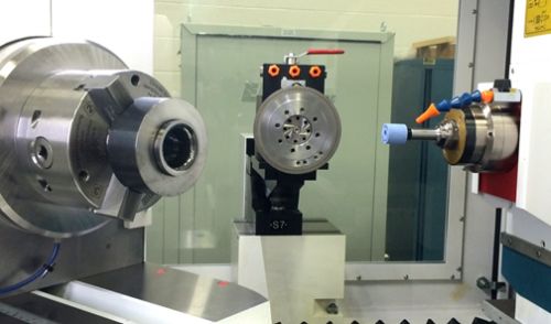
Figure 4b


Internal diameter (ID) grinding machines, like shown in figure 1a and 1b, are used to precisely condition the form, shape and finish of an inside diameter on your workpiece. Therefore, it’s important to understand how the relationships or alignment of key components to each other on the machine will affect the quality of the part being ground. If these key machine components are out of align by as little as 0.001" or 25.4 microns it could have significant consequences that contribute to poor part quality. Some operators may believe that truing or dressing a new grinding wheel means the wheel will have good cylindrical geometry. But if the grinding wheel spindle is out of alignment with the diamond truing device, the wheel form will not be accurately shaped. Issues can then occur during the ID grinding process that negatively affect part quality. The same can be said about the alignment of work spindle to grinding wheel spindle or both spindles to the machine’s X and Z slides. The information within this article should help example why it’s important to understand alignments and relationships of your machine’s components to each other and how this enables you to produce a quality workpiece.
The components on a basic ID grinding machine that need alignment maintained are the slides, both “X” and “Z,” the grinding wheel spindle, the grinding wheel truing/dressing device and the workhead spindle. Each component should be aligned correctly and checked to ensure they achieve the following requirements:


- “X” and “Z” slides must provide smooth and rigid straight line movements.
- Workhead and grinding wheel spindles’ centerlines must be in the same plane and parallel with the “Z” axis.
- Truing/dressing device contact point must be in the same plane that’s established by both workhead and grinding wheel spindles.
With the relationship of these components correctly set, your machine should have a straight line of contact between work and wheel. Poor part quality, like taper or “hour-glass” shape can occur in your work piece if there is a misalignment of the machine’s components.
X and Z Slides Must Provide Smooth and Rigid Straight Line Movements (Figure 2a)
If the “Z” slide wears and becomes slightly loose, the path that the grinding wheel travels will not be a straight line. This could cause the wheel to be dressed with a conical shape rather than a straight cylinder. When a conical shaped grinding wheel starts to grind the workpiece, the grinding wheel will first contact on the larger diameter side. The end result will be poor part form and surface finish. Excessive wheel wear may also occur. Therefore, be sure to inspect for rigid, smooth slide movement per your machine tool builder recommendations.
Workhead and Grinding Wheel Spindles’ Centerlines Must Be in the Same Plane and Parallel with the Z Axis. (Figure 2b)
In some manufacturing plants, it is common to have several grinding wheel spindles for one grinding machine to cover a wide range of wheel speeds. Different speed rated grinding wheel spindles allow for optimized wheel speed ranges needed to grind different part sizes. When one grinding wheel spindle is replaced with another, it’s important to check that the correct alignment is re-established. The new grinding wheel spindle centerline may be on the same vertical plane as work spindle and truing device but it could be off parallel horizontally with the Z axis and with the other centerlines. Grinding wheel spindles that are “off” parallel from the truing device can create a wheel OD that has taper trued into it or conical form. You can check if the grinding wheel spindle is horizontally parallel with the use of a magnetic base mount indicator. The indicator should have at least 0.0001" resolution. First, be safe and make sure none of the spindles are turned on or rotating. In machine setup mode, secure the base of the indicator to a fixed point on workhead spindle. The tip of the indictor will need to be set to touch on the horizontal side of the grinding wheel spindle diameter (at 3 or 6 o’clock) or on a grinding wheel quill that’s known to have a straight, consistent diameter. Once your indicator is set, slowly move the grinding wheel spindle slide in towards the workhead and then back. The slide travel length should be as long as possible. You should not see any more than 0.0002" deviation during slide travel. Repeat this process for the dressing system by securing the indicator base to a fixed point on the dresser system.
Another issue to be aware of when replacing grinding wheel spindles is to check that the spindle is not vertically tipped. A vertically tipped spindle would result with the spindle centerline not being on the same plane as work and dress system centerlines (Figure 3). When truing and dressing the wheel, the form can become “hourglass” or tapered shape. A poor shape dressed into the grinding wheel OD cannot produce a good quality workpiece. After replacing a grinding wheel spindle always 1) be sure to inspect that the spindle centerline height is in the same plane as the work spindle and dress system and 2) the grind wheel centerline is parallel with the centerlines of work spindle and dress system. This can be checked in the same manner described before for the horizontal alignment but set the tip of the indictor to touch on the vertical side of the grinding wheel spindle diameter (at 12 o’clock) or on a grinding wheel quill that’s known to have a straight, consistent diameter. The slide travel length should be as long as possible and you should not see any more than 0.0002" deviation during slide travel.
Truing/Dressing Device Contact Point Must Be in the Same Plane That’s Established By Both Workhead and Grind Wheel Spindles. (Figure 4a & 4b)
Today, many ID grinders can have more than one dress system available to use. This can require switching in and out different dress spindles or changing from a spindle to a stationary dress tool device. When changing any component on the machine you should always check that all components centerlines are on the correct vertical plane. Be sure that the point of contact across the wheel diameter is the same for both workpiece and dress system. This will assure proper form dressed on the wheel OD and the process should be able to maintain the tolerances required for your workpiece. When the grind mode is set up for “diamond sizing” or without an in-process gage the wheel or work is fed to a qualified end position. As the wheel gets dressed, the machine will automatically adjust its infeed travel amount to compensate for an increasingly smaller wheel diameter. This will maintain good finish part size, piece to piece. If the dress system centerline is significantly above or below the grinding wheel centerline your workpiece finish diameter will drift oversized. This is due to the machine’s dress compensation being set for a fixed amount each time the grinding wheel is dressed but the actual amount dressed off the wheel is less. Therefore, the machine compensates for the set in-feed dress amount but the wheel diameter is actually larger so your workpiece final size will trend oversize. There’s simple way to check if your dressing tool is on center with the grinding wheel diameter. First, be safe and make sure none of the spindles are turned on or rotating. Get a piece of flat ground steel stock that’s approximately a 6" long, ½" wide and 1/16" to 1/8" thick. In machine setup mode, move the grinding wheel towards the dressing tool. When you get close enough hold the flat stock vertically between the dressing tool and the grinding wheel. Now slowly continue to move the grinding wheel towards the dressing tool until the flat stock is lightly pinched between the grinding wheel and dressing tool. If the dressing tool is in the same plane as the grinding wheel spindle the piece of steel flat stock will remain vertical. If the dressing tool is contacting the grinding wheel below wheel centerline the flat stock with tip in towards the dressing tool. If the dressing tool is contacting the grinding wheel above wheel centerline the flat stock with tip in towards the grinding wheel. Consult machine tool builder recommendations on the best way to correct improper alignment.
The chart in the image box on the left shows different grinding wheel dress leads in “inches per wheel revolution.” Greater dress leads will “open” the wheel face and it will act sharper.
Remember take the time to inspect your ID grinding machine components. Be sure that they are correctly aligned to each other. A properly aligned ID grinding machine along with the right wheel specification and optimized grinding cycle parameters will be a very cost efficient method to produce your workpieces.


Related Content

How to Start a Swiss Machining Department From Scratch
When Shamrock Precision needed to cut production time of its bread-and-butter parts in half, it turned to a new type of machine tool and a new CAM system. Here’s how the company succeeded, despite the newness of it all.
Read More
Inside an Amish-Owned Family Machine Shop
Modern Machine Shop took an exclusive behind-the-scenes tour of an Amish-owned machine shop, where advanced machining technologies work alongside old-world traditions.
Read More
Volumetric Accuracy Is Key to Machining James Webb Telescope
To meet the extreme tolerance of the telescope’s beryllium mirrors, the manufacturer had to rely on stable horizontal machining centers with a high degree of consistency volumetric accuracy.
Read More
Buying a Lathe: The Basics
Lathes represent some of the oldest machining technology, but it’s still helpful to remember the basics when considering the purchase of a new turning machine.
Read MoreRead Next

The Cut Scene: The Finer Details of Large-Format Machining
Small details and features can have an outsized impact on large parts, such as Barbco’s collapsible utility drill head.
Read More

3 Mistakes That Cause CNC Programs to Fail
Despite enhancements to manufacturing technology, there are still issues today that can cause programs to fail. These failures can cause lost time, scrapped parts, damaged machines and even injured operators.
Read More