
Interpolating Curves
The ability to import complex curves into CNCs promises to let shops finally get beyond old limitations imposed by contouring with linear interpolation. Faster and smoother cutting will be the result.


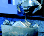
On this test piece, NURBS interpolation enabled Makino to achieve real feed rates as high as 1,000 ipm
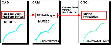
As GE Fanuc points out with this diagram, curve interpolation changes the fundamental approach to contouring program preparation and execution.
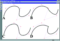
This illustration from Northwood Designs illustrates the power of NURBS. Curve "A" is a fourth order NURBS curve with 7 control points and 11 knots. Curve "B" has the weight on the lowest control point set to 0.1 instead of 1.0, showing how the weight affects the shape of the curve. Note the localized affect of this change. Curve "C" has only the knot sequence spaced differently, showing how knots help control the area that each control point affects. Curve "D" has the internal three knots at the same value, which forces the curve to hit the control point. Placing four knots in one place will clamp the end of a curve to a specific point.
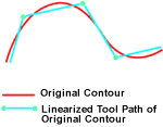
As this diagram from Siemens shows, linear interpolation is an inherently inaccurate way of representing curved forms. Thus, the many blocks of program data necessary to adequately approximate a form create downstream problems that limit real feed rates.
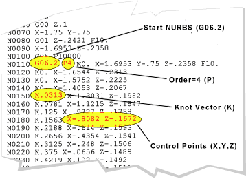
You've probably never seen a part program like this before. This sample output from EDS Unigraphics illustrates the GE Fanuc format for NURBS interpolation
For roughly the first 40 years of NC, there was really only one practical way to represent free-flowing curves in a cutter path. Even when CAD/CAM systems could mathematically define virtually any shape with smooth curves, those pristine forms inevitably had to be converted to a series of straight line segments in order to be executed on a numerically controlled machine tool.
In the early days of NC, this method was just fine. Indeed, it was a godsend to shops that heretofore had only tracer mills and hand-crafted patterns with which to control a curved cutter path—with no direct mathematical control at all. As CNC technology has progressed, however, the linear interpolation paradigm has come to be a limiting factor on the contour machining process. It is not accurate, forcing the machinist to work from an approximation of the true workpiece surface geometry rather than the real thing. It is not smooth—what should be a continuous contour is instead machined as a series of facets. It is not fast, because the desire to keep the facets small will limit the achievable feed rate. And it is not efficient, because the many lines required to approximate a contoured surface will swell part programs to enormous sizes, bogging down the process of transferring files from external computers into the CNC.


But it works. And until recently, there was little alternative. That is changing rapidly, however, now that an increasing number of CNC builders are incorporating complex curve interpolation capabilities into some of their controls. Finally, CNCs are beginning to "think" of contoured cutter paths in the same mathematical terms that CAD/CAM systems do. For machine shops—die and mold shops in particular—that's going to mean faster, smoother and more accurate machining of sculptured surfaces.
If you've heard anything about machining directly from curves, you've probably heard that capability referred to as "NURBS interpolation." That was the term coined by German control builder Siemens Energy & Automation (Elk Grove Village, Illinois) when they first introduced the capability several years ago. It's also the term used by GE Fanuc (Charlottesville, Virginia), which made a big splash with their NURBS interpolation capabilities last year. But there are also other kinds of curves that will offer essentially the same user benefits, though mathematicians will debate that point endlessly. Heidenhain (Schaumburg, Illinois), for instance, has recently introduced a curve interpolator based on cubic splines. Mitsubishi (Vernon Hills, Illinois) also reportedly has their own NURBS interpolator in the works.
Here's how the technology is emerging, and what it might mean to you.
A Word About Curves
The acronym "NURBS" stands for non-uniform rational B-splines, but if you're like most people, that information probably doesn't help very much. To get a handle on why CNC makers are moving to NURBS and other types of curve interpolation, we first have to back up and talk about CAD systems for a moment. The most basic entities CAD systems use to define 2D forms are line segments, circles, and arcs. While these constructs work well enough for defining relatively simple shapes, they quickly grow inadequate for designers seeking to create more complex, free-flowing forms. To deal with this limitation, CAD developers have over the years applied increasingly sophisticated mathematical curve formulas to give designers the tools to create precisely the forms they want and to manipulate those forms as they please. Here are some important curves to know about:
Simple splines are the CAD equivalent of the flexible steel rule that drafters have for years used to create free-flowing curves. The curve is defined by a sequential series of control points, much like pins on a drawing board. Once the coordinates of each control point are established, the computer then "connects the dots" with a smooth curve that literally intersects each point.
B-splines are quite different. They are defined only with endpoints and with control points that do not necessarily intersect the curve itself. Instead, they function essentially like gravity, generally pulling the curve in the control point's direction.
Non-uniform rational B-splines are of a higher mathematical order. Rational means that the weight of the control points' pull can be specified. And non-uniform means that the knot vector —which indicates which portion of a curve is affected by an individual control point—is not necessarily uniform. The upshot of it all is that more control factors can be applied to a formula so that considerably more complex forms can be expressed with a single curve.
While mathematicians and CAD developers can speak to the relative merits of these and other curve equations for hours on end, there are really only two essential issues for machine tool users to grasp. First, these are all mathematically based formulas that define the entire curve, not just intermittent points along the way. And second, because each higher level formula has more variables by which to define a curve, it has the mathematical capability to express exactly any curve created with a lower form. That's why NURBS has become the mother of all curve—and surface—definitions in CAD/CAM systems. It's the tool by which the most complex sculptured surface geometry can be created in a system, and it's a means by which that and other lower level geometry can be exactly exchanged from one system to another.
What's Wrong With Lines?
That exchange heretofore has been envisioned as being from one CAD/CAM system to another. But now it also can include an appropriately capable CNC, which brings up the first limitation of linear interpolation—accuracy.
In a conventional NC contour programming process, once the underlying surface geometry is created, the CAM system is going analyze that geometry, apply a user-specified tolerance, and then go about generating line segments joined end-to-end to create the final tool path. The tolerance—sometimes referred to as maximum chordal deviation—means that no point on the line segment will fall further from the reference geometry than the specified value, measured perpendicular to the line segment. So before the part program ever gets out of the CAD/CAM department, the tool path has already deviated from the ideal geometry.
That raises the second, and larger, issue—the tradeoff between accuracy and data volume. If the intent is to machine a smooth contour, a visibly faceted tool path is unacceptable in that it is obviously inaccurate and will require laborious hand finishing that degrades final accuracy even more. So the NC programmer sets the tolerance small to keep the line segments short and make the path as accurate and smooth as possible. But since each line segment corresponds to a block in the part program—expressed as an X-Y-Z coordinate "go-to"—the contouring program swells to enormous size.
Now two more issues arise. First, the gargantuan program probably won't all fit in the CNC memory, which necessitates some sort of external memory buffer at the machine tool or DNC link to drip feed the program to the CNC a little at a time. And second, in tight curves large numbers of go-to points will be clustered extremely close together, meaning more blocks for the CNC to process per unit of feed. These two factors form a tag-team that can significantly hamper the speed of the cutting process because the program can't be transferred to the CNC fast enough and/or the blocks can't be executed fast enough by the CNC to keep up with a desirable programmed feed rate. If the data stream intermittently runs dry for either reason, the feed is going to progress in fits and starts, which degrades surface finish, tool life, and maybe accuracy too if the tool is deflecting in an uncontrollable manner. And so the whole program feed rate is run slower than necessary, or the tolerance is set larger than desired, to avoid these problems.
At least, those are major issues with older controls. Newer high end CNCs have much larger memories, can achieve very high block processing speeds, and apply sophisticated look-ahead capabilities that scan ahead in the program for abrupt changes in cutter path direction. Real-time control algorithms not only see the turns coming, but also lower the feed rate in order to keep the cutter on path and avoid moments of data starvation. These features go a long way to alleviating the accuracy-vs.-data compromise necessitated by linear interpolation. Still, even with these extraordinarily capable CNCs, dense clusters of data points in the part program will significantly reduce the average real feed rate due to block processing limitations and because the control system must execute many abrupt local changes in path direction as it "corners" from each line segment to the next.
Enter The Curve
If you can import tool path curves into the CNC and machine directly from them, however, it's a very different picture. Ideally, the geometry need not be approximated at all. And because very free-flowing forms can be described with a single curve, part program size should be drastically reduced and block processing limitations rendered virtually irrelevant. We say "ideally" here because some practical tradeoffs of this technology are going to be in play for a while. Still, the benefits of curve interpolation are very real, with some companies having already demonstrated how they can work.
According to GE Fanuc, some CNCs have had the ability to internally spline point data in a conventional part program for a while now. For instance, that company has a feature called smoothing interpolation that "preprocesses a large CAM-generated linear interpolation part program into a smaller, NURBS-type format," they say. That helps with block processing problems and smoothes an otherwise faceted tool path. But they also point out a tolerance is applied in this curve-generation process that can compound tolerance errors that were generated by CAM in the initial part program.
The better solution is for the CNC to interpolate directly from the true curves generated in CAM, and that's what GE Fanuc is after with their NURBS interpolation feature. With it, the control reads a very different G-code than that to which machine shops are currently familiar. Rather than the X-Y-Z coordinates of a conventional program block, the NURBS data includes the control points, weights, and knot vectors required to define the curve. The control builder contends that this method of representing curved cutter paths "results in a reduction of program size of 1/10th to 1/100th of a comparable linear interpolation part program and significantly improves the fundamental accuracy issues."
The accuracies of such capabilities are becoming increasingly well documented in high speed machining applications. Indeed, Siemens claims that "in existing applications, accuracies of 0.5 micron with feeds of 400 ipm were reached" with NURBS interpolation on that company's much touted 840D control.
But curve interpolation can also be used simply to go flat-out faster than ever before, since the CNC interpolates the original curve at the CNC's interpolation rate. How much faster? It's hard to say at this point, and many machine tool builders are asking themselves the same question. But we got a tantalizing insight into the issue earlier this summer in the demo area of machine tool builder Makino (Mason, Ohio).
Makino CAD/CAM applications engineer Jeff Wallace believes that NURBS interpolation will result in feed rates being boosted by "at least 30 percent and maybe as much as 50," and has been conducting cutting tests to bear out that hypothesis. To demonstrate, Mr. Wallace showed us the curvy test part being cut on one of Makino's high speed machining centers fit with a GE Fanuc M C control. To see just how fast the machine could contour the foot-long, P20 piece, the path was programmed at a feed rate of 999 ipm and the feed rate override was set at 200 percent. When planar (X-Z) cuts were first executed in a conventional linear interpolation mode, the actual feed rate topped out at about 650 ipm. Then Mr. Wallace switched over to a NURBS representation of the same path, leaving all other parameters unchanged, and immediately the feed began breaking 1,000 ipm at its fastest moments.
That's not going to happen on just any machine tool, of course. But it does nonetheless illustrate the potential of curve interpolation that has captured the attention of high speed machine builders worldwide.
Programming Issues
There will be much debate in the coming few years over who has the best curve interpolator, much of it based on the math behind the curves themselves. As mentioned earlier, not all curve interpolators are NURBS based. And even if they are, there are several orders of NURBS, which is going to render some NURBS interpolators more mathematically capable than others, though also more processor intensive to compute.
However, those arguments are probably way beyond what's going to matter most to the average shop, particularly given where they are coming from in terms of their existing technology. The far larger issue for now is how to get a good set of curves into a control to begin with, and that returns us to the CAD/CAM department.
The good news is that a number of CAM developers are now actively developing curve output capabilities. One of the early players is EDS Unigraphics (Maryland Heights, Missouri), which already has the capability to post process programs to the NURBS-based formats used respectively by Siemens and GE Fanuc, as well as polynomial formats also used by Siemens and now Heidenhain.
But outputting curves directly from a CAM system isn't the only alternative. For example, the MetaCut system from Northwood Designs, Inc. (Antwerp, New York) can take a conventional part program and convert it to curves for the major control formats. According to company president Bill Elliott, the system was originally configured to convert linear interpolation programs to arcs executed with circular interpolation, and for the very same reasons that curve interpolation is now coming to address. But the checks and balances they developed to correctly fit arcs is applicable to the NURBS-fitting algorithms as well. The system reads in the point data presented in a program and systematically fits curves to that data based on a specified tolerance, and then outputs curve interpolation commands.
Detractors will no doubt argue that this method retains the double-tolerancing issue, first creating the points in CAM and then again with the curve-fitting routine. What they'll miss with this argument, however, is that a CAM system that directly outputs curves probably does it the same way—it just happens internally so the user doesn't see the process. This is not a knock on CAM systems. For several technical reasons, it is a daunting challenge for a CAM tool path processor to output the base surface geometry directly. If that still sounds like a compromise, consider that now the point data can be generated with extremely small tolerances because the size of that file is irrelevant to the machining process. Then when those points are splined, the output curves should provide a considerably closer representation of the base geometry than the conventional approach of linear interpolation. As one CAM developer puts it, working with the point data is the "low hanging fruit" that lets developers deploy current technology to generate output curves that do a significantly better job of representing the base geometry than line segments ever could.
But let us not make too much of the accuracy issue, at least within the context of most 3D contouring applications. As Mr. Elliott puts it, "While the specific shape and accuracy of a airfoil may be critical, this isn't always the case with a mold. You may be more concerned with surface finish than high accuracy, and accomplishing this is the next level of curve machining. In the short term, the greatest gains to be expected from curve machining are reduced machining times and a somewhat smoother surface finish."
Curve interpolation, like any new technology, has its own limitations to work out. And to be sure, much development work is yet to be done by CAD/CAM, CNC, and machine tool builders to bring this technology to the average shop. But curve interpolation does indeed appear to be the future of high performance contouring, and will soon be a better tool than we've ever had before.


Related Content

Integrated CAD/CAM Promotes Process Efficiency, Traceability
High-requirement markets are not only searching for good parts — they're searching for proof of good parts. CAD/CAM software can help.
Read More
CAD/CAM System Requirements: An Overview
CAD/CAM programs are among the most demanding kinds of computer software. Smooth operation requires careful consideration of computer specifications.
Read More
Grinding Simulation Enables Growth in Custom Tooling
Simulation software both streamlines Gorilla Mill's grinding machine setups and speeds up the company's tooling design and verification processes.
Read More
Large-Format Machining With Small Cutting Tools and Dynamic Motion
Napoleon Machine, a defense contractor that provides parts for the M1 Abrams tank, recently took advantage of a CAM feature that allowed the company to streamline its cutting strategies and program offline. Here’s how the shop cut cycle times nearly in half with its large-format five-axis machining operations.
Read MoreRead Next

3 Mistakes That Cause CNC Programs to Fail
Despite enhancements to manufacturing technology, there are still issues today that can cause programs to fail. These failures can cause lost time, scrapped parts, damaged machines and even injured operators.
Read More

The Cut Scene: The Finer Details of Large-Format Machining
Small details and features can have an outsized impact on large parts, such as Barbco’s collapsible utility drill head.
Read More