Lights Off, Profit On
Various tooling considerations contribute to profitable lights-out machining.
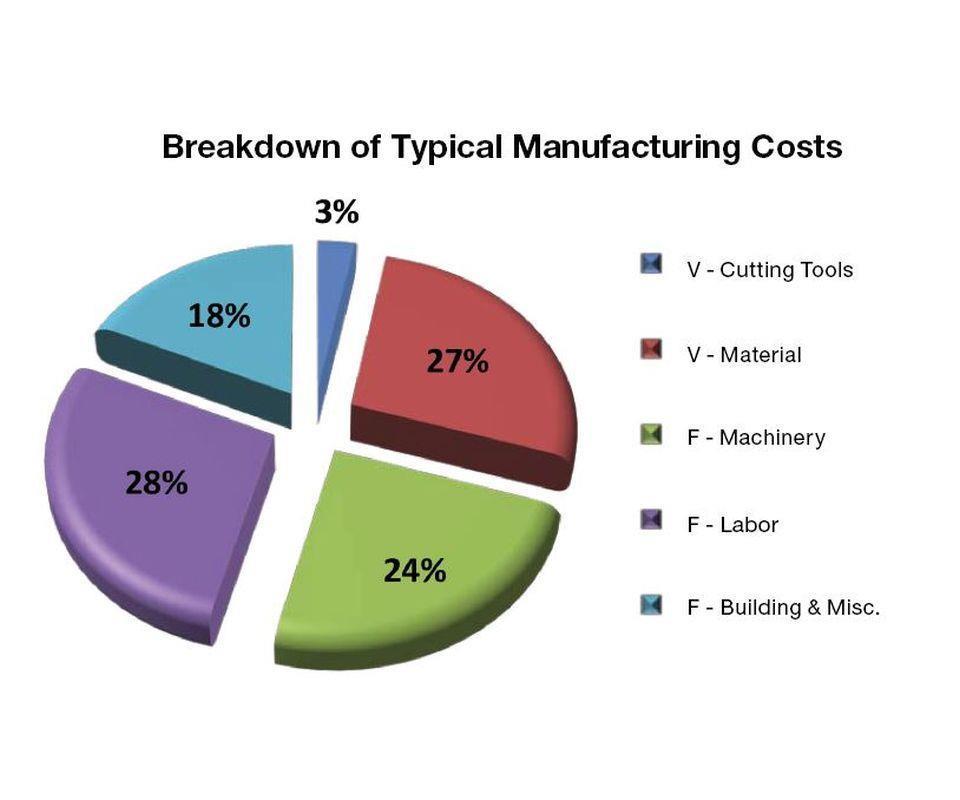
Cutting tools (a variable cost) are a small contributor to the total unit cost of a machined part.
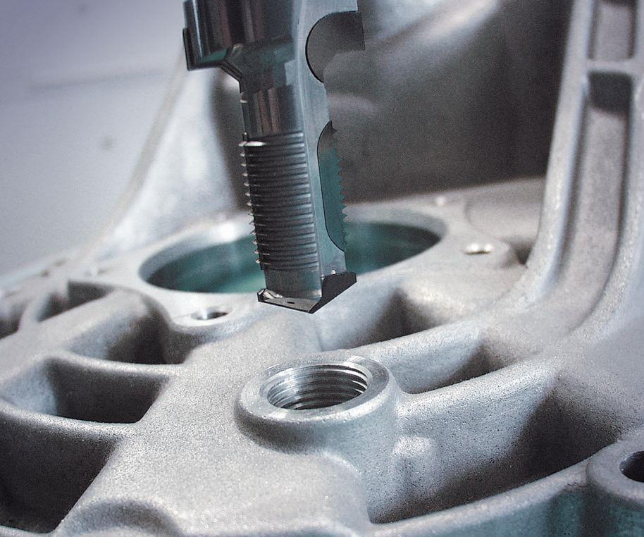
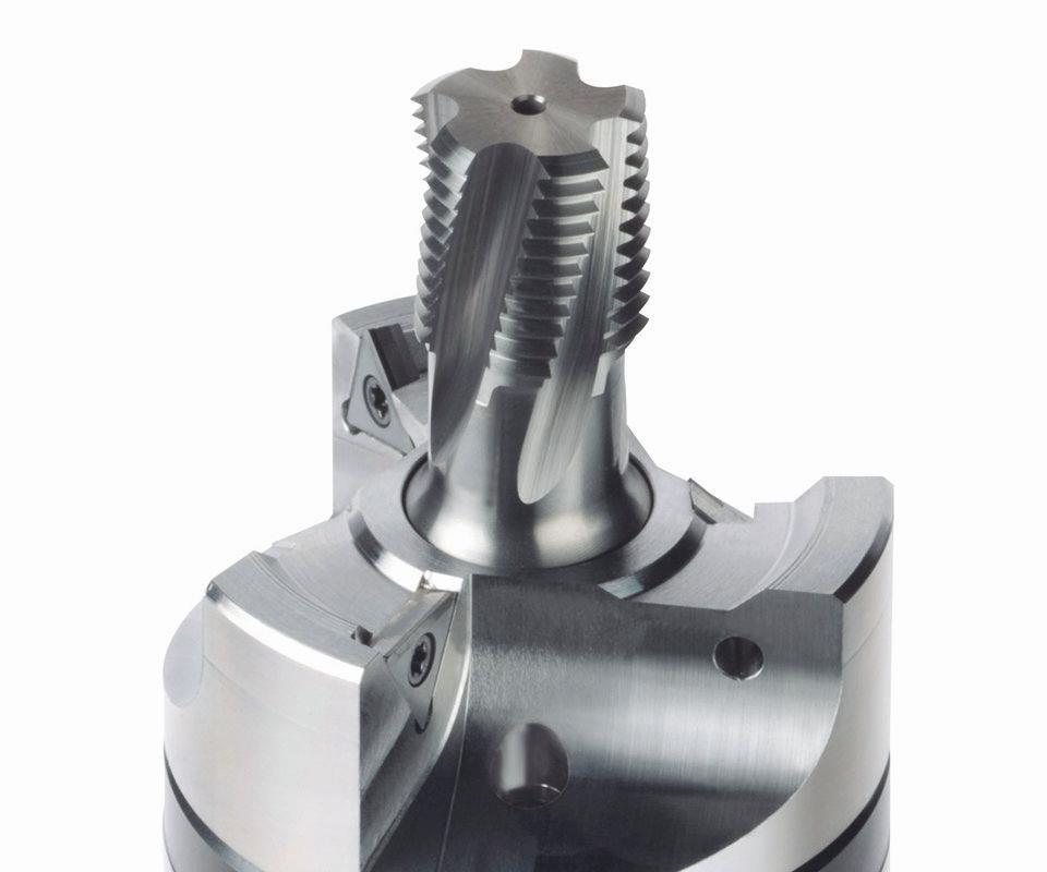
Combination tools contribute to a more efficient and predictable process by consolidating multiple cuts in one tool. The photo at the start of the article also shows a combination tool.
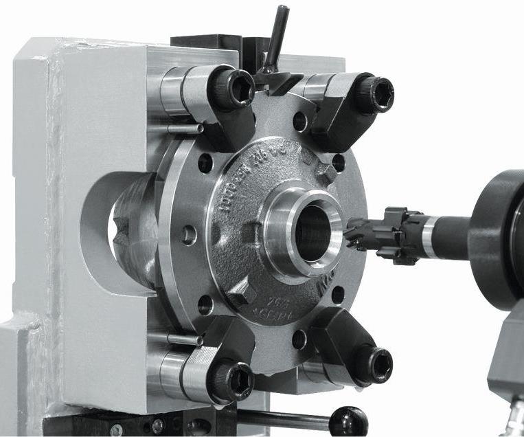
This modular tool system, Komet’s Vabos, uses a changeable center tool with a holder featuring indexable cutting edges.
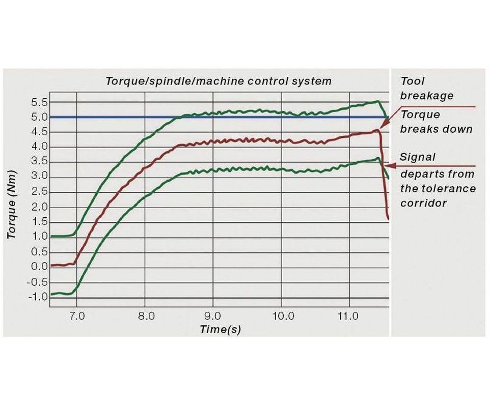
Dynamic monitoring completes the lights-out machining process.
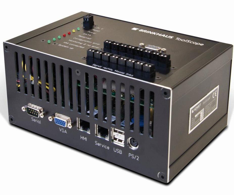
The hardware for one such system is seen here. During tool breakages, the system’s tolerance limits are violated, triggering a fault signal.


All manufacturing operations have fixed and variable costs, and fixed costs are generally the larger of the two. Fixed costs include overhead such as capital expenses for buildings, equipment, and the utilities required to use and maintain them. However, labor is the largest component of fixed costs, and reducing the amount of that expense in the unit cost of each part is the focus of lights-out manufacturing.
Variable costs, on the other hand, include those for tooling and material. Material costs can be managed through wise choices in the size and type of raw stock, and through reducing the amount of scrap. Tooling is usually one of the lowest cost areas of all—typically around 3 percent of the overall cost of the part. Yet tooling can also be the most dynamic component of the process in that it can reduce or increase cost in other areas, including both material and labor.


That is why the direct cost of the tool is rarely as important as what the tool can do. If reducing the direct cost of cutting tools negatively affects the performance of the process, then cost increases in other areas will easily overcome the savings from using less expensive tooling. By contrast, significant savings in the overall cost of machining each part can come from tool choices that help shops realize lights-out manufacturing.
Stability
To achieve a true unattended manufacturing operation, the key is process stability. A stable operation will produce a consistent number of parts, cycle after cycle. If a stable process cannot be maintained, then trying to run lights-out is futile. An operator will be needed to monitor the system and fix problems as they arise, increasing labor and tooling costs, and potentially increasing material and maintenance costs as well through scrap parts and machine damage. This stability is not just a result of the tool choice, but rather a result of every part of the system working together. Problems in one area, such as weak fixturing or an inconsistent coolant supply, may show up as tool breakage that is difficult to predict or control.
Perhaps the most important factor in creating a stable machining process is optimizing the cutting conditions. Cutting tools are designed to perform under a specific range of conditions relative to the load on the cutting edge (resulting from the feed rate) and temperature at the cutting edge (resulting from the speed). Using parameters that are too slow or too fast have equally negative effects on process stability through their impact on tool life, chip evacuation and part quality, as well as their contribution to tool failure.
For example, high-performance taps are tools that are frequently used at a much slower speed than they were designed for, often leading to tool breakage and therefore system instability. One variety of tap, for instance (KOMET’s Morex R carbide-strip roll-form tap), has a recommended surface speed ranging to 80 surface meters per minute in carbon steel. For an M10 tap, that is a tapping speed of faster than 2,500 rpm. Assuming the machine can accelerate fast enough to even achieve that speed before decelerating towards the bottom of the hole, any drastic increase in speed beyond this limit would overcome the heat rating of the coating and tool substrate, reducing tool life and thread quality, and contributing to premature failure. A minimum surface speed of 30 surface meters per minute is also recommended for that same application, yielding a tapping speed of 955 rpm. Again, if the speed were drastically reduced from that figure, then the tool likely would not generate enough heat for the material to form the thread consistently, and this would result in too much torque, eventually breaking the tap.
With drills, meanwhile, the most important factors are stability on entry or exit from the material, along with chip evacuation within the cut. Almost any drill point design will create a chip, but if the flute design cannot adequately and consistently evacuate the chips from the drill point, then the chips will become compacted in the flutes and the drill will break due to a torque spike.
The chip size and shape are determined by the drill point or insert geometry and the feed rate. A given flute shape may be optimized to handle particular chips, but as the feed rate increases or decreases, so does the chip size and shape, and the needs of evacuating those chips. It is important, therefore, to use the tool within its designed feed rate limits to ensure productivity without random tool failure.
All cutting tool designs also need to be matched to the toolholder and its limits. A tool with a long length-to-diameter (L:D) ratio will react very differently to high radial loads than will a toolholder that is short and rigid. Stable cutting conditions change as the L:D ratio changes. Other factors that are critical are tool runout and holding strength. Tool runout that is too high will reduce the stability of the system. The same is true for holding strength; if this is not adequate for the forces generated by the cutting tool, there is a risk of tool pullout.
Shrink-fit tooling systems have grown in popularity because they have such good runout, grip strength and radial-load capabilities. However, shrink-fit is not the “end-all” of toolholding systems. In particular, applications involving a long L:D ratio, a thin-wall component or a weak fixture are prone to chatter or harmonic vibration. In these cases, toolholders that have a damping property or mechanism are often effective for overcoming this vibration effect.
Improvement and Monitoring
The next phase of lights-out machining is to improve upon a stable process to further reduce the cost per unit. The main way to successfully achieve this is to increase product throughput by machining more parts faster without failure. While faster machines reducing non-cutting time can cut down on cycle time and increase throughput, changing machines is often not feasible. The next step, therefore, is to look at different tools that can achieve and maintain faster operating parameters. The difference may be an improved design, coating, substrate or other feature of the cutting tool. Or, it may be an entirely different tool concept.
Specifically, one way the choice of cutting tools can improve overall unit cost is through the use of special combination or hybrid tools. By using custom-engineered combination tools, it is possible to reduce the total number of tools required to machine a specific component, also reducing both tool-change time and the non-cutting time in the cycle during which the tool is repositioned. A tool such as this might be a carbide step drill that creates a hole, counterbore and chamfer, where previously that operation took three standard tools. Such a tool might also be a customized straddle mill that machines features on multiple sides of a part at once, or a tool that can produce a back chamfer by circular interpolation after another part of the tool is used to create a stepped bore. Some modular tool systems use a changeable center tool such as a “thriller” that can drill, chamfer and thread mill, combined with a holder that features an indexable or brazed cutting surface that creates a larger spotface or counterbore feature that otherwise couldn’t be accomplished using a single tool design due to the diameter differences. Combination and custom-engineered tools offer a way to simultaneously increase throughput and increase stability and confidence in the machining system.
One additional part of a successful and profitable lights-out manufacturing system is process monitoring. Random failures will happen, and they won’t always be caught by systems built into the machine. A broken tap not detected, for example, could run hundreds or thousands of non-conforming parts in a lights-out shift. A process monitoring system detects faults such as this by measuring forces on the machine generated by cutting and comparing them to a programmed standard. If the forces deviate from a calculated mean by a given amount, the process can be programmed to stop, with notification sent to a specific person or a back-up tool called to replace the problem tool so production can continue. The monitoring system also responds to the absence of a load. In the case of the broken tap, if the tap cycle runs and the monitoring system does not register a spindle load where that load should occur, it again can stop the machine from continuing and call a back-up tool.
In fact, a tool monitoring system such as this actually facilitates automatic inspection. Detail of a hard casting can be documented and tracked based on the tool load when it is cut—a quality-assurance consideration that many flight-critical components need. Monitoring systems are thus the final piece that can unlock the potential of lights-out manufacturing systems.


Related Content

Shop Quotes Smarter, Works Harder with Machine Monitoring
Temco first installed MT-LINKi to optimize quoting. Now, the software helps the shop optimize its machines — and machine purchases.
Read More
Swiss-Type Control Uses CNC Data to Improve Efficiency
Advanced controls for Swiss-type CNC lathes uses machine data to prevent tool collisions, saving setup time and scrap costs.
Read More
Give Job Shop Digitalization a Customer Focus
Implementing the integrated digital technologies and automation that enhance the customer's experience should be a priority for job shops and contract manufacturers.
Read More
Finally, A Comprehensive Software Solution Designed for Small Job Shops
Zel X from Siemens is an integrated software application that consolidates collaboration, design, manufacturing, and operations into a comprehensive, easy-to-use solution. From RFQ to delivery, it’s a more efficient way to handle quotes, manage jobs, make parts, and collaborate with teams of all sizes.
Read MoreRead Next

The Cut Scene: The Finer Details of Large-Format Machining
Small details and features can have an outsized impact on large parts, such as Barbco’s collapsible utility drill head.
Read More
3 Mistakes That Cause CNC Programs to Fail
Despite enhancements to manufacturing technology, there are still issues today that can cause programs to fail. These failures can cause lost time, scrapped parts, damaged machines and even injured operators.
Read More
