
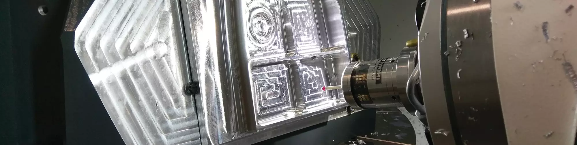

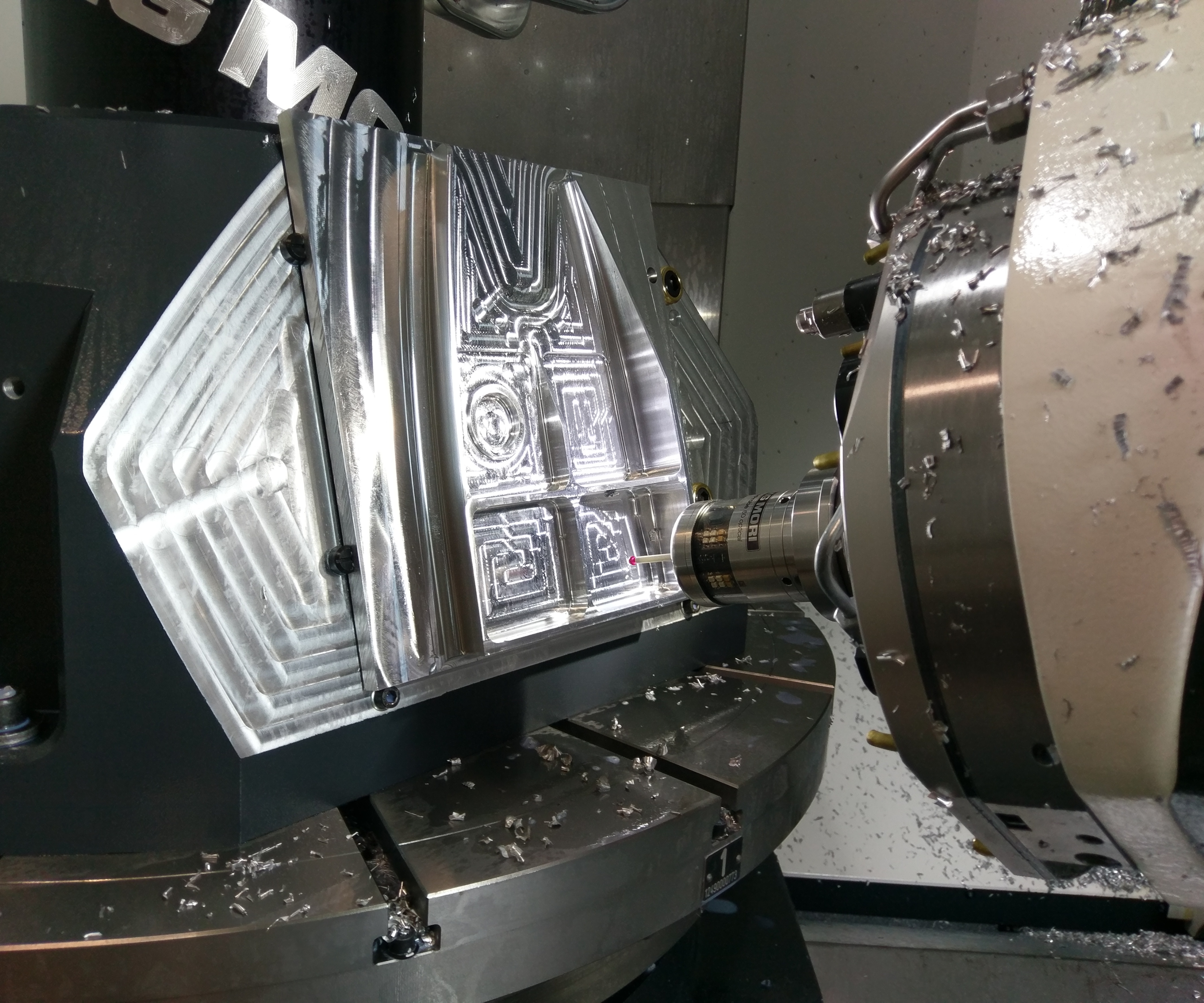
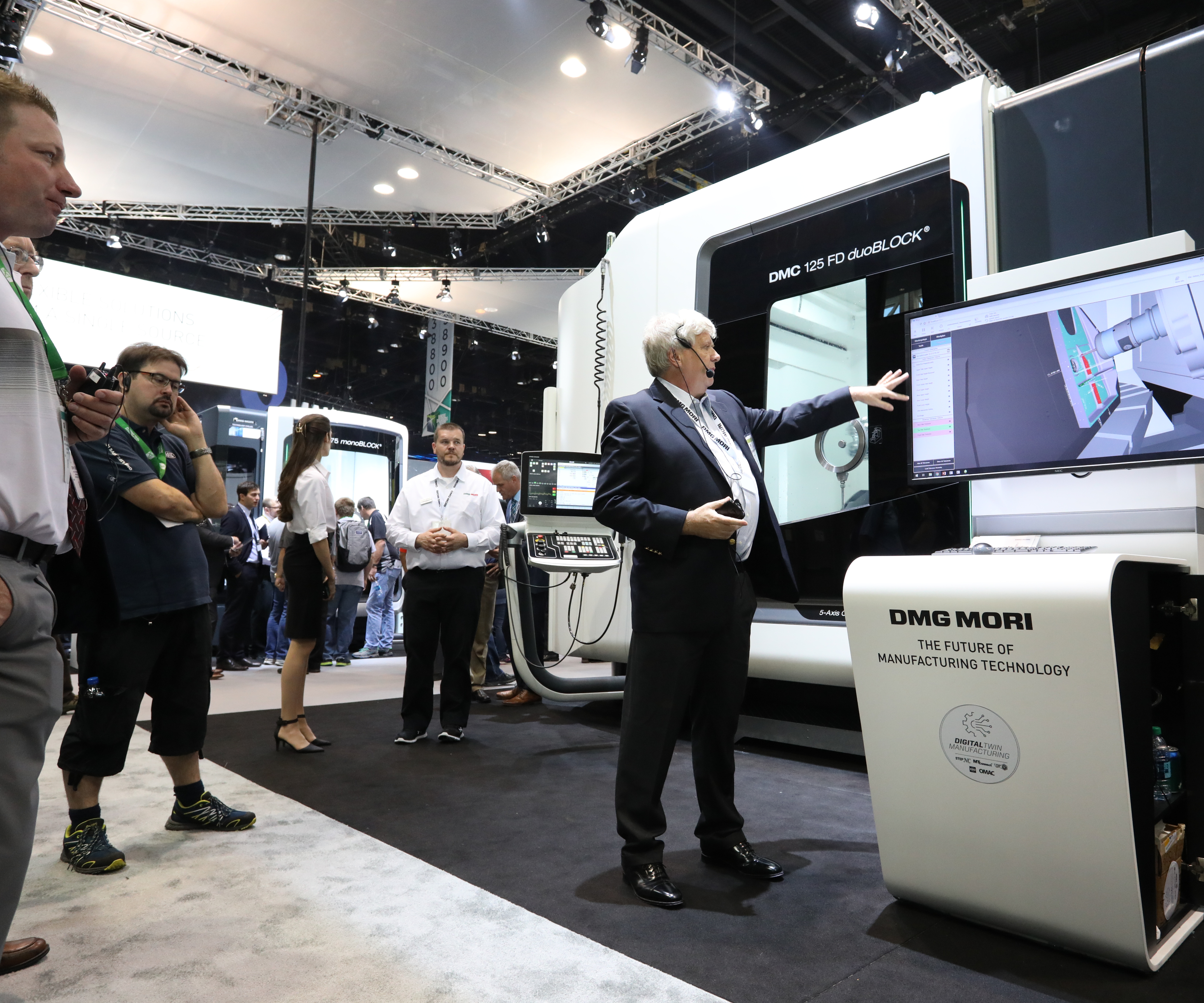
For the “Grand Challenge” at IMTS, the Airbus-designed, Boeing-programmed test part was machined in two booths on two machining centers. The part is shown here on the DMC 125FD Duoblock mill-turn machine in the DMG MORI booth. (Image courtesy of DMG MORI.)
The same part was produced on an XF6300 five-axis vertical machining center in the Hyundai WIA booth. The machining centers in the two builders’ booths had different configurations.
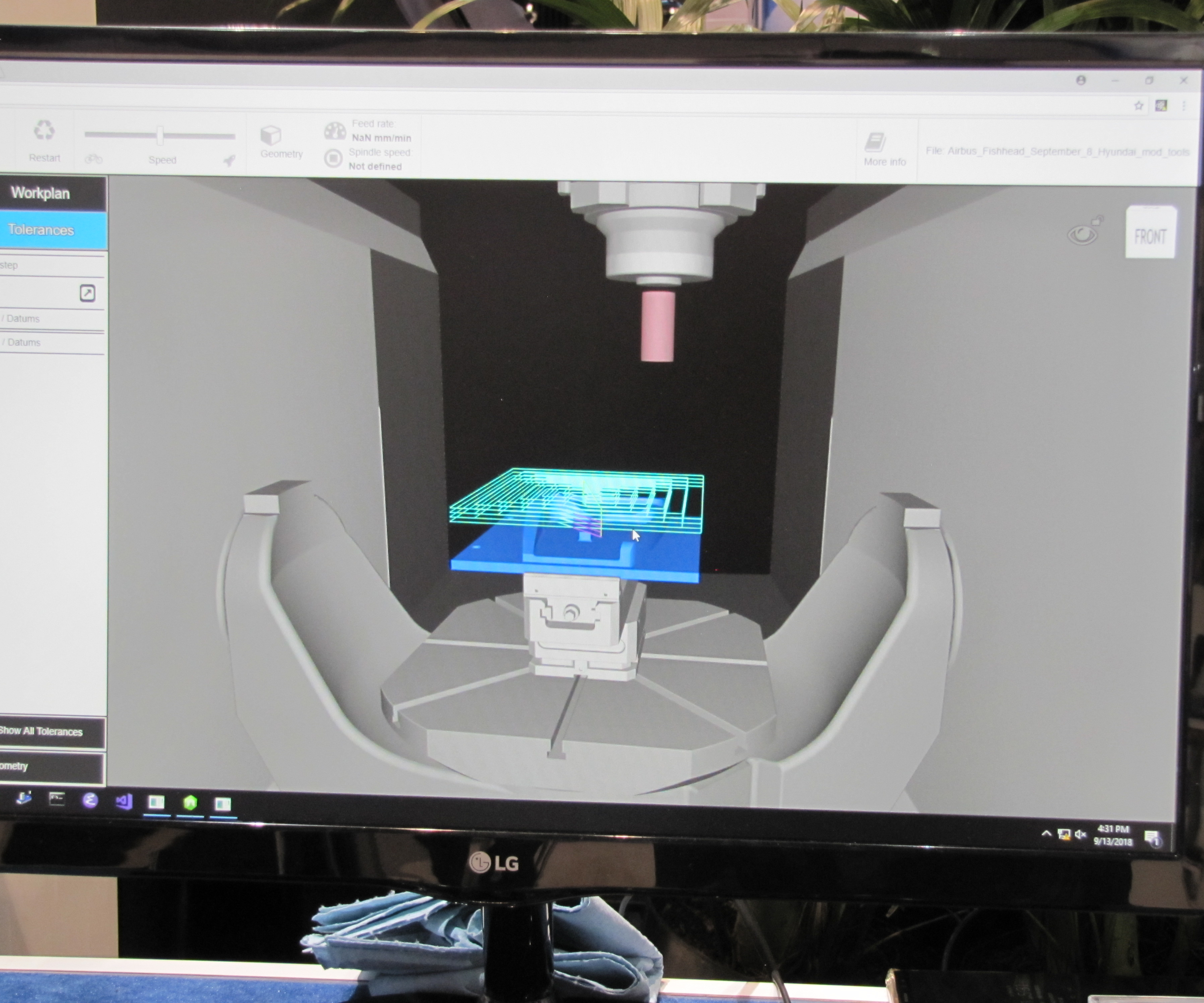
Digital models of the machining process were shown on large screens in each booth. During machining, the models showed progressive results of metal-removal operations in real time. This view was part of a live presentation in the Hyundai WIA booth.
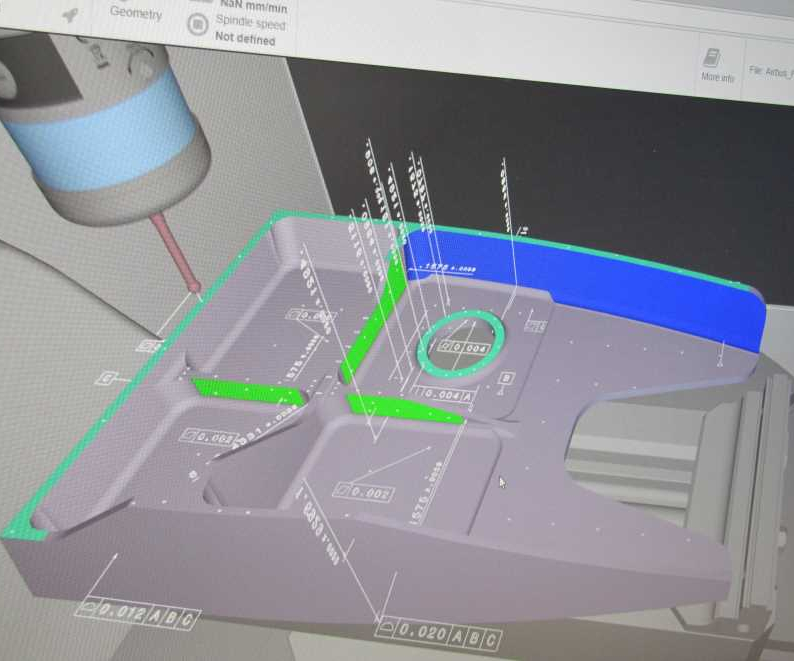
Results of on-machine probing also were displayed in real time. GD&T data associated with critical features enabled results to be color-coded to indicate the status. The data-rich virtual model of the machined part represents its digital twin.
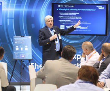
Dr. Martin Hardwick of STEP Tools Inc. explained the details of the Grand Challenge in live presentations during the show. (Image courtesy of DMG MORI.)


If you have wondered what digital twins mean to manufacturing and what they promise for machining complex parts, a successful demonstration of this concept was presented at the International Manufacturing Technology Show (IMTS) last September in Chicago, Illinois. Called the “Grand Challenge,” the demonstration was intended to prove that today’s digital technology enables manufacturers to use computer-generated models for producing a part, inspecting it, and verifying that it meets all specifications and requirements, even when portions of the production process are handled by different suppliers using different equipment. If this concept was shown to work at IMTS, it would work equally well for shops and manufacturers in the field, the demonstration sponsors say.
Because these computer models serve as digital twins of the entire manufacturing process, it is feasible to use them to replicate setups or move work-in-process more readily from supplier to supplier while maintaining production accuracy and consistency. This capability is said to give prime contractors and their base of capable machined-parts suppliers greater flexibility, smoother collaboration and fewer bottlenecks that can interfere with supply-chain flow. It is significant that this demonstration had the advantage of using existing, well-established manufacturing standards for exchangeability and interoperability, such as components of Standard for the Exchange of Product (STEP) model data, the MTConnect semantic vocabulary for manufacturing devices and the Quality Information Format (QIF) metrology standard.


On to the Demonstration
The Grand Challenge was sponsored by the Organization for Machine Automation and Control’s OMAC Manufacturing Workgroup and the International Standards Organization (ISO) Working Group TC184/SC4/WG15, which is involved in the development and support of STEP manufacturing data standards. The effort was led by Dr. Martin Hardwick of STEP Tools Inc. (Troy, New York) and Rensselear Polytechnic Institute. While many other technology suppliers and users have been involved in digital-thread and digital-twin efforts over the years, the primary participants in the Grand Challenge were machine tool builders DMG MORI and Hyundai WIA, metrology companies Renishaw and Mitutoyo, cutting tool supplier Sandvik Coromant, as well as Boeing representing the end-user community.
For the demonstration, Airbus developed a test five-axis aerospace part. Boeing then added geometric dimensioning and tolerancing (GD&T) call-outs and created a base process, including stock definition, cutting tool requirements and four “stage models,” each defining the results of three- and five-axis roughing and finishing operations. All this information was translated into a single, non-proprietary STEP file and sent to DMG MORI and Hyundai WIA. Standing in as representatives for shops in the field, both companies developed manufacturing processes optimized for some of the machining centers they had in their IMTS booths. During the show, each company machined the test part and verified that it met all dimensional tolerances and specifications after each operation.
A key aspect of the demonstration was to show how two contract manufacturers (represented by DMG MORI and Hyundai WIA) could share a production job between themselves without losing efficiency or effectiveness, a result that is highly desirable in the real world but often difficult to achieve. Part processing was divided into two steps. The two machine tool builders alternately performed roughing operations on a machining center in their booths, then sent the digital results to each other for finish machining and on-machine part probing. Alternating the assigned operations highlighted the strength of the digital-data format (STEP and associated programming technologies) and the process of communicating it using MTConnect. Thus, the two companies were able to show how one could pick up where the other left off and still produce a part in which the program data and inspection criteria did not regress.
Although the production of components at different locations is nothing new, the manner in which this was done, using digital-thread and digital-twin concepts, reveals present and potential gains in efficiency and flexibility. For example, because the cutting tools were defined using the ISO 13399 format, acquisition and use of them was simplified. As a result, Sandvik Cormorant was able to provide automatically generated setup sheets. The 3D cutting tool models were also included in the STEP file for import into the different CAM systems DMG MORI and Hyundai WIA used. Having all this information in a standard format enabled the creation of a digital twin of the part while it was being machined. The actual creation of the digital twin used software from STEP Tools and an MTConnect connection to the machine tools’ Siemens 840D controls. During machining, axis motion was sampled and combined with the STEP data, creating the digital twin. Observers watched the machining of the digital twin alongside the machining of the physical part and saw that changes in the physical process, such as different feed rate overrides, were reflected in the digital twin.
During the manufacturing process, the part was inspected on each machine using a Renishaw touch probe. Again, this is nothing new, but the manner in which the probing functions were developed and what was done with the resulting data showed the flexibility and usefulness of the digital twin. Because the GD&T information was defined in the STEP file and directly linked to the geometry, it was not necessary to manually transfer this same information to the NC program, and functionality was available to help define the inspection process. Likewise, because the GD&T requirements and inspection process were linked to the design features, the probing results could be easily linked to the relevant geometry. The result was the merging of the probing results and the digital twin. Here again, observers could see this occurring in real time. The digital twin showed not only numerical values, but also offered color coding of the features to demonstrate how close the machined part was to nominal dimensions.
The intuitive nature of the inspection results’ graphical representation was further demonstrated through QIF, the new standard supporting digital-thread and digital-twin concepts that was developed by the Digital Metrology Standards Consortium as a replacement for the dimensional measuring interface standard (DMIS), an older standard for exchanging metrology data. In the demonstration, a QIF representation of the inspection results was automatically generated, merged with the digital twin and used by Mitutoyo to validate the accuracy of the digital twin measured during on-machine inspection, as well as confirm results using a coordinate measuring machine. Again, the process was demonstrably simpler and more intuitive by using standard data formats and having the GD&T information linked to the actual geometry.
In addition, the demonstration presented a scenario in which, during machining, the digital twin could be shared remotely via secure internet connections. Thus, results of machining could be monitored and analyzed in real time. For example, if measurements made on the virtual model indicated that tolerances were not being met, an alert could be sent to the machine operator for adjustment. Likewise, because the data embodied in the digital twin is entirely linked to part features, they can be analyzed further to monitor processes and improve them.
Answering Critical Questions
According to Dr. Hardwick, success of the demonstration was contingent upon STEP, MTConnect and QIF working together seamlessly to apply digital-twin technology to part production. STEP is essential for describing the model data in a format interpretable by the CNCs, enabling tool paths to be described with the dimensions and tolerances that must be met by the results of machining, he says. MTConnect enables machine tool coordinates to be streamed in real time and shared in a digital format to produce a record of what the machine was doing during execution of the toolpath commands. Similarly, QIF enables results of quality evaluations to be reported and shared. Dr. Hardwick says QIF complements MTConnect by enabling causes of an out-of-tolerance condition to be traced to its effect.
To emphasize the importance of these three standards, Dr. Hardwick explains that, together, they enable the goal of “build it here, build it now and build it right.” “Build here,” he says, “means being able to make a part at the local machining resource because of interoperability. Build now means being able to make a part without delay or hesitation because on-machine simulation and verification ascertain capability. Build right means being able to make a part correctly and to specification because metrology systems give immediate feedback.”
In other words, at every step in the process, there has to be a nearly perfect match between the real and the ideal, he says. That is, a match between physical objects and their digital counterparts. For machining, this means what is true about the virtual computer models will be true about the workpiece.
“This is the value of the digital twin,” Dr. Hardwick contends. “Now the speed, portability, analytical power and record-keeping capacity of computer technology converge with physical reality. If you grasp this point, the concept of digital-twin manufacturing makes sense and becomes a compelling reason to embrace it as an approach to making parts.”
However, there is a need for further development and acceptance of the underlying technology demonstrated at IMTS, he adds. For example, CNC manufacturers and CAM software developers must continue to create interfaces that more fully support interpretation of STEP models. In addition, MTConnect and QIF standards have yet to formalize all vocabulary definitions and data tags, especially in areas that ensure compatibility of machining and measuring expectations.
A Team of Rivals
Although the demonstration sponsors say the Grand Challenge met all of its objectives, it also represented another achievement not to be underestimated. The demonstration represented the extraordinary cooperation and effort among the participants. As a representative of one participating company, David Odendahl, associate technical fellow for Boeing Production Engineering, says, “The test part was designed by Airbus, programmed by Boeing, machined by DMG MORI and Hyundai WIA, and inspected by measurement systems from Renishaw and Mitutoyo. These companies are frequently in competitive situations, but they worked side-by-side on this project for a common purpose.”
The importance of the Grand Challenge is also confirmed by the judgments of the participants. James Nudo, president of DMG MORI USA, says “The digital twin accelerates and stabilizes all customer processes. It produces a virtual component parallel to the real machine. This combination of information from the real and virtual worlds is a decisive step for DMG MORI and our customers to increase the planning quality and speed on the shop floor. Our customers are enthusiastic about digital engineering, especially about the direct tracking of information in real time and the visualization of component quality.”
Most important to the manufacturing community at large, the demonstration presented a compelling case for working toward a better understanding of the digital-twin machining concept as well as taking steps for its implementation.


Related Content

Shop Quotes Smarter, Works Harder with Machine Monitoring
Temco first installed MT-LINKi to optimize quoting. Now, the software helps the shop optimize its machines — and machine purchases.
Read More
Machine Monitoring Boosts Aerospace Manufacturer's Utilization
Once it had a bird’s eye view of various data points across its shops, this aerospace manufacturer raised its utilization by 27% in nine months.
Read More
Diving Deeper Into Machine Monitoring Data
Data visualization is the first step in using machine monitoring data, but taking it to the next level requires looking for trends within the data.
Read More
Can Connecting ERP to Machine Tool Monitoring Address the Workforce Challenge?
It can if RFID tags are added. Here is how this startup sees a local Internet of Things aiding CNC machine shops.
Read MoreRead Next


3 Mistakes That Cause CNC Programs to Fail
Despite enhancements to manufacturing technology, there are still issues today that can cause programs to fail. These failures can cause lost time, scrapped parts, damaged machines and even injured operators.
Read More
The Cut Scene: The Finer Details of Large-Format Machining
Small details and features can have an outsized impact on large parts, such as Barbco’s collapsible utility drill head.
Read More