
Machining’s Role In Making Cancer "History"
A machine shop in a new cancer treatment center produces components to precisely guide proton radiation to eliminate its target—cancerous tumors.
.jpg;width=70;height=70;mode=crop;format=webp)


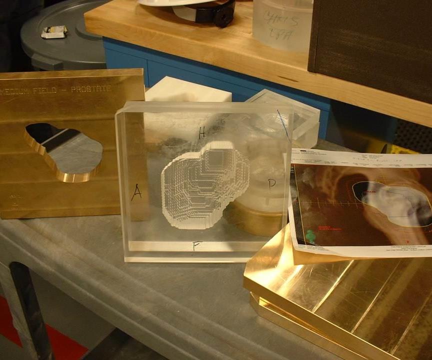
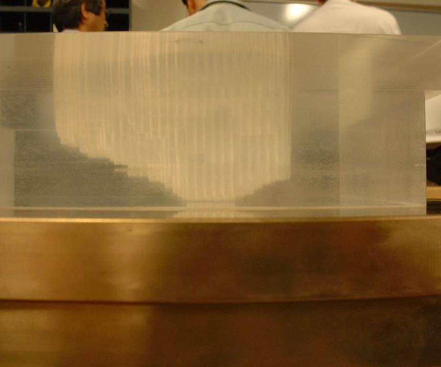
The brass apertures for the proton therapy laser system have a simple window to shape a proton beam, while the acrylic compensators have a pixilated cavity that focuses the beam to strike a tumor.
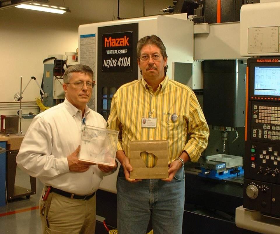
John Barr (left) and Paul Wisdom hold the two main components this cancer treatment center will produce—brass apertures and acrylic compensators.
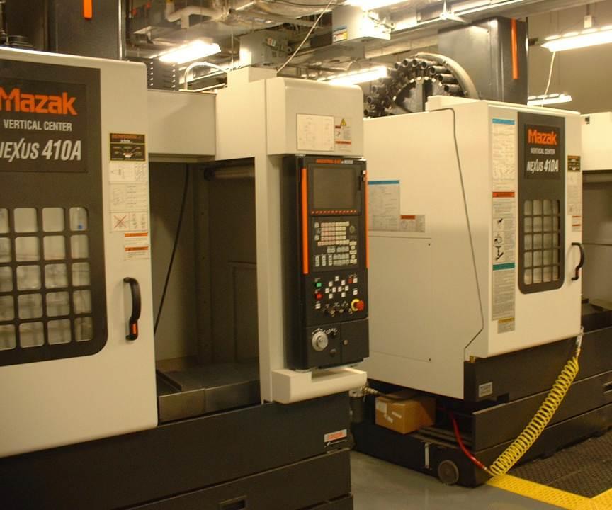
Four networked CNC VMCs will be called on to support the center’s production needs.
Each feature through-spindle coolant and a tool presetting sensor.
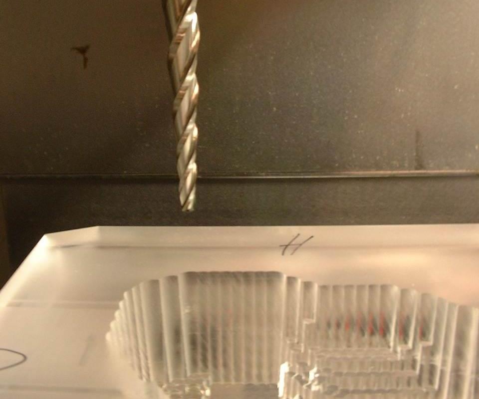
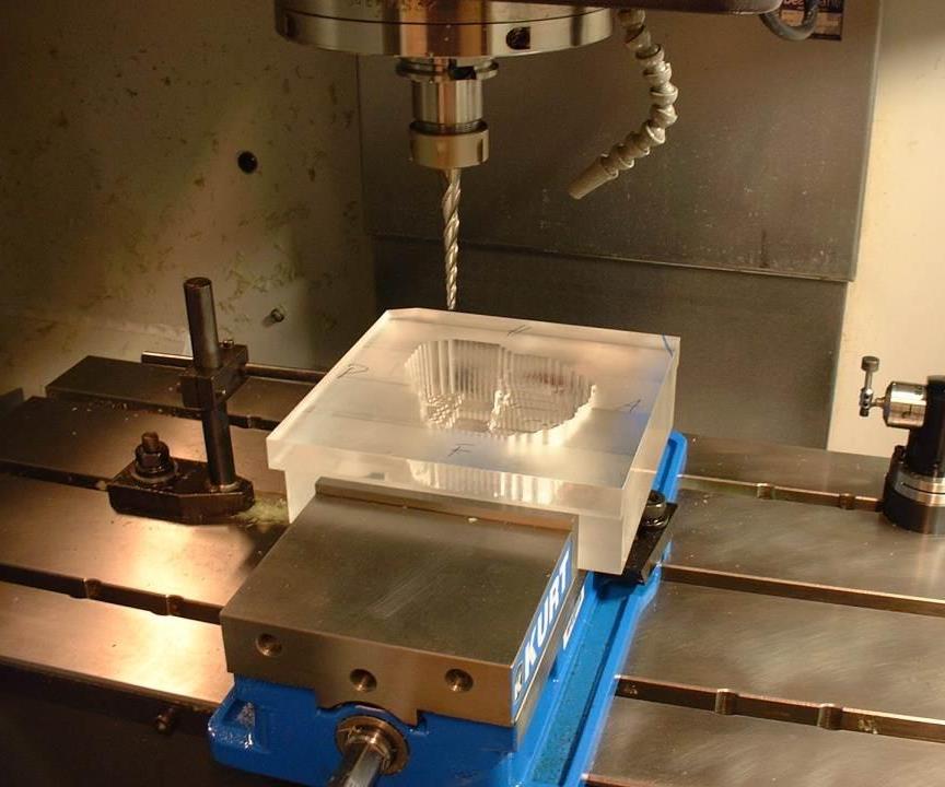
Tapered end mills allow deep plunges with relatively small tip diameter.
The tools also create the 3-degree wall taper required for the compensators.
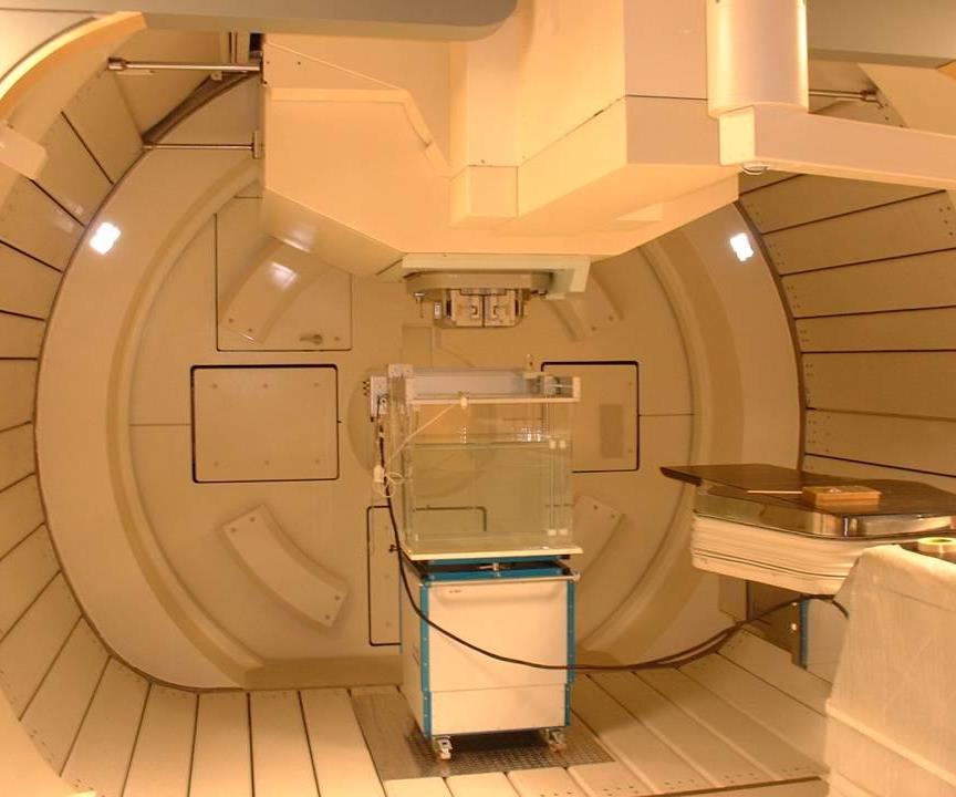
This rotating beam delivery gantry weighs as much as a Boeing 757, but it can deliver proton beams to 0.5-mm positioning accuracy.
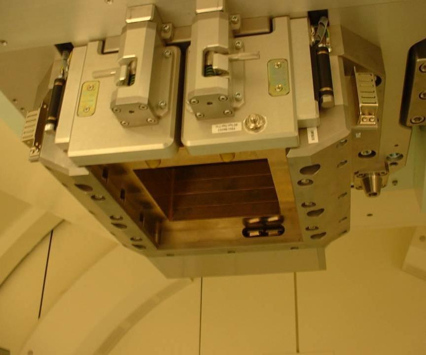
The apertures and compensators produced in the shop slide into this gantry snout.
Medical and metalworking technologies meld in an effort to heal in Houston, Texas. The two disciplines are working in concert to make cancer “history” at M.D. Anderson’s new Proton Therapy Center, located in the heart of the Lone Star State’s largest city.
One of only four proton radiation centers in the United States, M.D. Anderson’s $125 million facility will serve more patients than any of the other centers, treating 3,500 per year when it reaches full capacity. In order to support such an aggressive treatment schedule, the facility houses its own machine shop that includes four networked CNC vertical machining centers (VMCs).


The primary duty of these machines is to produce two patient-specific components for the center’s gantries, or radiation beam delivery devices. One of these components is a brass aperture that receives a window to shape the beam to match a tumor field’s outline. The other is an acrylic compensator block into which is machined a cavity to shape the beam to release its energy at the appropriate depth within the patient’s body. The ability to manipulate the beam in a way that damages a cancerous tumor without harming nearby healthy tissue is what makes proton therapy such a precise and powerful cancer treatment.
Most hospital-based machine shops are equipped with toolroom-type mills and lathes that are used to produce one-off fixtures or instruments. The shop at M.D. Anderson’s proton therapy center does have such equipment for that type of work. However, it is first and foremost a production shop, as John Barr points out. Mr. Barr, the shop’s supervisor, selected most of the shop’s machine tools and related equipment. Four Mazak Nexus 410 VMCs will bear the brunt of the shop’s production work. When the center reaches full capacity, those machines will produce thousands of apertures and compensators each year.
Modern Machine Shop was invited to tour the center and its dedicated shop a few months in advance of the official opening in June 2006. During the visit, Mr. Barr and Paul Wisdom, a deft machinist who is currently “on loan” from M.D. Anderson’s nearby instrument shop, explained the role that machining technology plays in support of an effective cancer treatment procedure.
Protons Pack A Punch
The 94,000-square-foot facility is topped by an open, inviting entrance with numerous offices and examination rooms. However, the building is an iceberg of sorts, because 42 feet of it is below ground. Located in this bunker are four proton radiation treatment rooms and the compact machine shop that measures 36 by 44 feet. These rooms are surrounded by 8-foot-thick concrete walls and a ceiling that’s 12 feet thick. The subterranean location and beefy enclosure are required to contain stray radiation during treatment.
The apertures and compensators are the final two components in the subatomic beam delivery process. An injector first strips protons from the nucleus of hydrogen atoms and delivers them to a synchrotron, or particle accelerator. The synchrotron, essentially a magnetic “racetrack,” accelerates the protons in a vacuum to an energy level approaching 250 million electron volts. The protons then travel at nearly light speed to rotating beam-delivery gantries located in three of the four treatment rooms. Though the huge gantries measure 35 feet in diameter and weigh 190 tons, they rotate smoothly, quietly and precisely 360 degrees around a patient and direct the proton beam to 0.5-mm positioning accuracy. The aperture plates (as many as four identical 2-cm-thick plates may be required) and compensator are inserted into the gantry’s snout to shape and focus the beam as it exits the gantry en route to the targeted tumor.
The protons enter the a patient’s body at a low energy level, peak their energy level within the tumor and effectively stop there so that surrounding healthy tissue is left unharmed. Apertures and compensators are matched sets specific to each patient and each different beam delivery angle into a patient’s body. While no two sets of apertures and compensators are alike, the process for creating these components is the same for all.
Machining From A CAT Scan
The brass aperture plates and acrylic compensator blocks are first squared and face milled to size. The brass is machined dry; the acrylic is machined using high-pressure coolant. One corner of each component receives a notch, which serves as a key to ensure that the components are properly oriented when installed in a gantry snout.
The shapes of the aperture window and compensator cavity are determined by a model of the patient’s tumor, which is obtained via a computed tomography scan, or CAT scan. The CAT scan captures the tumor volume one thin 2D slice at a time. The 2D images, taken at discrete depths throughout the tumor, stack together to create what is essentially a 3D model of the tumor. The electronic tumor model is part of each patient’s file in the IMPAC treatment planning system, which the shop can access via the network.
The apertures come in three standard square sizes, and all are 2 centimeters thick. The window shape, which matches the perimeter of the tumor, is machined using a high-helix-angle 0.25-inch end mill from Iscar (Arlington, Texas), which is generally small enough to produce the tightest of window radii. The tool first plunges into the middle of the window location and then spirals out to net shape. Typically three passes/cutting depths are taken to machine away the entire window. A finish pass removing between 0.005 to 0.01 inch is then performed to generate a quality wall surface finish.
The format of the CAT scan data essentially drives how the compensators are machined. The scan data is arranged in a set of X and Y positions and string of Z-axis depths. Because a CAM package can’t recognize this format, an intermediate piece of software is required. Developed by Hitachi, the company that manufactured the gantries, in conjunction with the Proton Therapy Center, the software translates the scan data into a text-file format with X, Y and Z coordinates to allow GibbsCAM from Gibbs and Associates (Moorpark, California) to generate machining code.
Because the data for the compensator cavity is a set of X-Y positions with specific Z-axis depths, the cavities are created by plunging a tapered end mill from Garr Tool (Alma, Michigan) to the proper depth at each position. Tapered end mills are used for a couple of reasons. First, although the tapered tools may have tip diameters measuring only 3, 4 or 5 mm, their tapered shanks offer rigidity to plunge deeply into material without breaking. This might not be possible using a small-diameter straight end mill with a high L/D ratio. Second, tapered tools automatically create the requisite 3-degree wall angle while the compensator remains fixtured flat on the machine table. Machining in this drilling-like motion leaves behind the compensator’s typical “pixilated” cavity finish. A smooth, contoured finish is not required for proton radiation therapy.
Compensator cavities can have several thousand X-Y positions, depending on the size of the tumor field and cutting tool diameter. The machines are not cutting to a specific Z-axis depth, per se, but rather to a height above a 1-mm datum common to all compensators. After the interface creates the text file with machining code, Mr. Wisdom edits the part program slightly before sending it to one of the networked VMCs. That’s because every point located on the compensator’s top plane, including those positions that require no machining for the cavity, is represented in the part program. Without editing, the machine would drive the cutting tool to every listed X-Y position on the square face, lowering the tool just to the block’s top surface for those areas outside the periphery of the cavity. To eliminate this wasted tool movement, Mr. Wisdom selects a single point on the top plane of the compensator just before actual machining would start (the point just before the top-left-most point of the cavity) and then deletes all of the other points so that the cutter is moved to that chosen point to start the machining cycle.
Is There A Better Way?
At the time of our visit, Mr. Barr and Mr. Wisdom had all the essential programming, tooling and equipment in place to support the center’s production needs. According to Mr. Barr, process refinement is the next step, specifically in some of the areas that follow. As you read about the shop’s possible improvement areas, call to mind your own machining practices and ask yourself the same questions Mr. Barr and Mr. Wisdom are asking themselves: “Is there a better way . . .”
. . . to secure workpieces? The center’s shop currently uses vises as its primary workholding method for the apertures and compensators. This strategy will probably change. Because all compensator blocks are the same size and there are only three different aperture plate sizes, the shop will likely develop dedicated fixtures with some sort of quick-release clamp for faster change-overs. Vacuum workholding tables are an alternative for the compensators, given that the bottoms of those parts are completely flat and all points making up the cavity are located relative to the bottom, which is the Z-axis zero. A vacuum fixture would ensure that the part is completely pulled down on the table, whereas an operator must make sure the part does not tilt or lift when tightening a vise.
Would an alternate workholding method be appropriate for your shop? If you are machining a lot of ferrous materials, then perhaps magnetic workholding would offer access to five sides of a part. If dedicated fixtures may be used, then it would be helpful to create them so that there is only one way a workpiece can be installed in the fixture (this is known as poka yoke), to avoid the chance that an inexperienced employee will secure the part incorrectly.
. . . to select and use cutting tools? Mr. Barr and Mr. Wisdom are always following latest trends and technologies related to cutting tools and coatings. They typically don’t let the initial price be the determining factor. They purchased a Renishaw TS27R toolsetter with each VMC so that all tools in toolchanger are measured and ready to cut when called upon.
Would a specialized cutter be appropriate for your work? Consider the payback in terms of longer tool life, better surface finish and increased production rather than focusing solely on tool price.
. . . to handle material? The center must address material transport and handling issues, given the shop’s basement-like location and the weight of the brass aperture blanks. The 2-cm-thick plates, which weigh approximately 40 pounds each, exert a significant amount of pressure on an operator’s lower back when they are loaded into a machine tool. Mr. Barr is considering some sort of support cart and roller conveyor not only to ease workpiece loading into the machine tools, but also for treatment workers to load apertures into the gantry nozzles.
Are there alternate ways to transport stock and work in process (WIP) throughout your shop? Could you make better use of work carts? Regarding machine layout, is there a better way to allow parts to flow from machine to machine? Is there room for a tow motor to maneuver where it needs to be?
. . . to schedule work? Effective job scheduling will become more important as the center’s shop ramps up production. The cycle time for apertures may be only 5 minutes each, versus up to 3 hours for compensators, so Mr. Barr will have to decide how to best schedule jobs and use machines.
Is there a way to schedule jobs to facilitate kitting to allow all components of an assembly can be machined together and shipped out? Would there be value in setting up multiple workpieces and chaining part programs together to allow longer unattended machining?
. . . to provide a little extra? The center has a Prototrak lathe and Trak mill (these machines are available from Southwestern Industries, located in Rancho Dominguez, California) for prototype, fixturing and other miscellaneous work to support the center. Mr. Barr chose these hybrid machines because they could run either manually or by CNC program. To best respond to various manufacturing needs per the devices thrown its way, Mr. Barr stocked the shop with equipment that includes a surface grinder, knee mills, table saw, band saw, TIG welder and heat treatment oven.
Similarly, are there other capabilities, perhaps outside of traditional chip-making equipment, that you could add to your shop’s arsenal? Perhaps you machine parts that also require secondary processes such as marking, anodizing or heat treat. Offering these additional services or possibly some component assembly might also be helpful for customers and make use of any downtime machine operators may have while waiting for a machine tool to finish its cuts.


Related Content

A New Milling 101: Milling Forces and Formulas
The forces involved in the milling process can be quantified, thus allowing mathematical tools to predict and control these forces. Formulas for calculating these forces accurately make it possible to optimize the quality of milling operations.
Read More
Best Practices: Machining Difficult Materials
Cutting hardened steel, titanium and other difficult materials requires picking the right tools, eliminating spindle runout and relying on best practices to achieve tight part tolerances.
Read More
Ceratizit's Updated Tooling Solutions Improve Machining Performance
The company has upgraded its EcoCut indexable inserts lineup, as well as introduced two new toolholding and workholding solutions.
Read More
All-Around Mill Improves Productivity and Cost for Valve Job
Adopting a mill with a double-negative rake and pockets compatible with multiple insert geometries enabled Progressive Metal Service to increase feed and lower scrap rates for a valve.
Read MoreRead Next

Handle With Care
Micro-size drills and end mills don’t have to be difficult to use.
Read More
The Cut Scene: The Finer Details of Large-Format Machining
Small details and features can have an outsized impact on large parts, such as Barbco’s collapsible utility drill head.
Read More
