
Making Mountains out of Mold Steel—Literally
When graphite molds wouldn’t cut it for a manufacturer of hand-blown drinking glasses, this shop machined more durable stainless steel molds to create the famous mountainous shapes that emerge from the bottom of its customer’s nifty drinkware.
.jpg;width=70;height=70;mode=crop;format=webp)
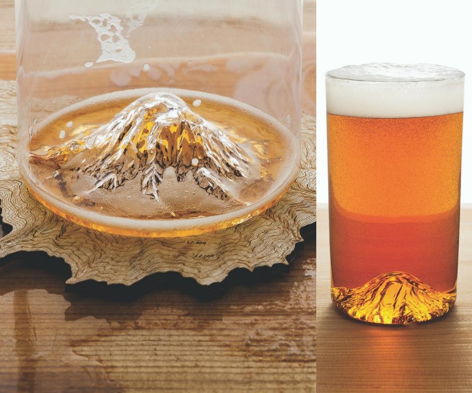
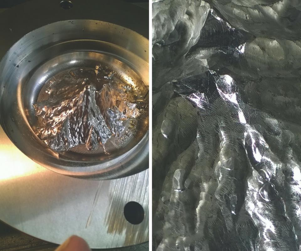
A good deal of intricate machining work capped by finishing with a 0.030-inch ball end mill goes into manufacturing the stainless-steel molds for this hand-blown North Drinkware glass that features an accurate representation of northern Oregon’s Mount Hood. (Photos courtesy North Drinkware.)
El desbaste del molde comienza con una fresa de extremo plano de 0,5 pulgadas. Eventualmente, estos se maquinan con una fresa de extremo de bola de 0.030 pulgadas. El taller mecaniza planos en dos lados de la parte inferior de los moldes cilíndricos para que el tornillo de banco se agarre.
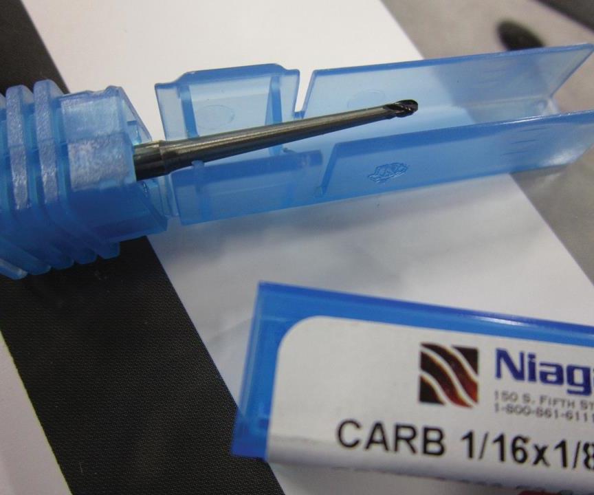
C&L utiliza principalmente herramientas de Niagara Cutters. Para esta herramienta, el taller rectificó el vástago de esta fresa de bola de 1/16 de pulgada para permitirle mecanizar un calado de 0.5 grados en la ladera de la montaña California Half Dome.
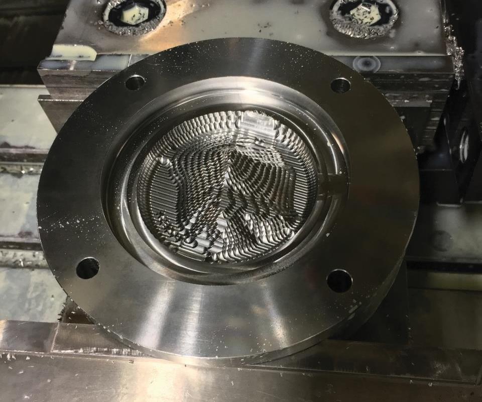
Esto da una idea de los detalles nítidos que las máquinas C&L introducen en estos moldes de acero inoxidable. Este componente de molde base se atornilla a un componente cilíndrico hueco para formar el molde completo.
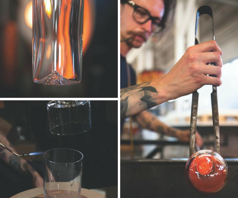
Los artesanos necesitan dos días y más de 15 pasos para crear un vaso North Drinkware soplado a mano. La compañía ofrece actualmente cuatro diseños de montaña (tres con montañas de la costa oeste y uno con una montaña de la costa este), pero actualmente está trabajando en un quinto diseño. (Fotos cortesía de North Drinkware).


Bottoms up.
That is to say, the uniqueness of the glass pints and tumblers hand-blown by artisans for North Drinkware grows upwards from the base of those glasses as accurate representations of iconic U.S. mountains. The photos in the slideshow above show what I mean.


A couple of years ago, Nic Ramirez, along with husband and wife team Matt and Leigh Capozzi, started a highly successful Kickstarter campaign near Portland, Oregon, to fund a side project they named North Drinkware. In short, their idea was to partner with nearby Elements Glass to manufacture hand-blown beverage glasses that had the shape of Mount Hood, Oregon’s highest peak at 11,250 feet, molded into their bases. The team felt this would offer local craft beer drinkers a unique connection to their scenic area in the Pacific Northwest.
To start, North Drinkware used United States Geological Survey (USGS) 3D data of Mount Hood to develop a CAD model of the mountain. It then 3D-printed that model to create and refine plaster prototype molds, ultimately hiring Portland’s C and L Custom Tooling to machine the first production mold from graphite. After that, North Drinkware started its “Oregon Pint” Kickstarter campaign to support the fledgling company’s growth efforts and vision for creating glasses featuring other famous U.S. mountains. In fact, this campaign with a $15,000 goal closed at $531,581 with funding provided by 5,620 backers, signifying significant interest in the idea.
However, the first glass-production molds led to production problems. The first problem was finding a shop to machine the molds. North Drinkware approached C and L first, knowing that the shop, which specializes in injection mold tooling design and machining, was successfully branching out into mold machining for local custom glass manufacturers. Unfortunately, Glen Sparkman, C and L’s co-owner with wife Donna, says their three-person shop was simply too busy at that time to take on the job. North Drinkware tried another shop, but that one wasn’t able to generate the crisp mountain details the company was looking for, so it waited until C and L’s schedule opened up a bit.
Eventually, C and L produced the type of detailed graphite molds that North Drinkware needed to begin production. Over time, however, those molds, which are heated to 600°F during the molding process, began to break down. Essentially, the molten glass would stick to the molds and pull away bits of graphite when the blown glass was removed from them.
Therefore, the decision was made to switch to stainless steel, an alloy commonly used for production-glass molding applications. This material ultimately held up longer, only requiring periodic repolishing. That said, compared with graphite, it was much trickier to machine the intricate mountain details. “Graphite wasn’t too difficult when using a 0.030-inch-diameter ball end mill for finishing, but it became a different story when moving to stainless steel,” Mr. Sparkman says.
Although one might think the process for machining these types of features with such small tools might involve machines with very high spindle speeds, C and L uses a VMC with a maximum spindle speed of 8,000 rpm. As Mr. Sparkman described during my recent visit, the process he developed for these finely detailed molds is not appropriate for the typical high-volume job in which minimizing cycle times is key, but it is necessary for one-off/low-volume jobs such as machining these stainless-steel molds. In fact, he’s since applied this process to create three other mountain mold designs for North Drinkware, with another design currently in the works.
All about the Details
The molds are created from two pieces: a cylinder that C and L turns on its Femco lathe to create the outer shape of the blown glass, with a taper where it meets the separate base component that includes the mountain shape. Although Mr. Sparkman is provided with a CAD model of the mountain, he typically uses repair tools in Solidworks to patch areas where model data is missing and to create the mold design. From that, he uses Surfcam to create tool paths that are designed not to bury small-diameter tools in corners to prevent tool breakage.
The base mold components are machined on the shop’s Chevalier 2040 VMC. Mr. Sparkman says he purchased this boxway machine with 8,000-rpm spindle for its flexibility to accommodate anything from graphite to tool steel. He admits that, while a more specialized, high-rpm machine might be more appropriate for producing the fine details the mountain molds have, he believes it makes more sense for his shop to have a versatile machine that can run a variety of jobs rather than a more costly high-speed machine that might sit idle waiting for the right work. Plus, even though the process for machining the mountain molds can be rather long, he can run longer programs unattended overnight.
A base mold component starts from a length of round bar with flats milled at the bottom so it can be secured on the VMC with a conventional vise. Mr. Sparkman says he uses Niagara Cutter tools for these jobs, some featuring titanium aluminum nitride (TiAlN) coatings and others using titanium carbo-nitride (TiCN), because they perform well, have minimal runout and are reasonably priced.
Dennis Noland, senior design and R&D engineer at Niagara Cutter, says the thinness of the coatings (in the range of 3 to 5 microns) is especially important for micro-tools like the ones C and L uses. (He defines micro-tools as tools having a diameter smaller than 0.100-inch.) That’s because there’s not as much rounding on the cutting edges, and the tool surface finish is smoother because there are fewer droplets left behind from the coating process.
In addition, Mr. Noland notes that stepovers for such small-diameter tools should be no more than 8 to 10 percent of the tool diameter, especially when a very smooth workpiece surface finish is required.
What follows is the series of milling operations Mr. Sparkman commonly uses for these stainless production molds. He starts with two-axis, roughing contour and cuts around the mountain shape, and this is followed by a three-axis Z-roughing operation. Next is a Surfcam three-axis Auto Rough tool path followed by a three-axis Planar tool path, which cuts multiple surfaces at one time in a straight-line path, generating a 0.001-inch-tall scallop height. Machining is completed using successively smaller ball end mills (the last being a 0.030-inch-diameter tool) and the 3-Axis Steep/Shallow tool path, which provides constant 3D offset based upon surface angle and overlap specifications to produce an equal scallop height of 0.0002 inch.
In addition to proper tooling and toolpath selection, Mr. Sparkman says coolant type plays a key role, too. The shop uses Oemeta’s Hycut two-component water-soluble metalworking fluid, which is based on synthetic ester oils that are said to offer high lubricating performance and reduced tool wear. (This product has also been certified by the USDA under its BioPrefered program.) The company’s Hycut CF 21 cutting oil is combined with Additive BF and added to the machine’s sump. This offers the ability to mix the two components in any number of different ratios to dial in the correct amount of lubricity depending on the application. (The mixture used for the stainless steel molds is highly lubricious to more effectively machine the “gummy” stainless steel material.) The two-component concept also yields a longer shelf life for the oil and additive compared to pre-mixed coolant, because the components are stored separately and blended together only as needed.
More Mountains on the Horizon
After machining, Mr. Sparkman hand-polishes the mold’s mountain features. To date, C and L has created molds for four different North Drinkware mountain designs (Mount Hood, Washington’s Mount Rainier, Vermont’s Camel’s Hump and Half Dome in Yosemite National Park). For very popular glass products that are produced in greater volumes, it has machined duplicate molds. Plus, the molds do become slightly corroded due to the high operational temperature range, so they require C and L to repolish them every few months.
The deft, manual work that goes into hand-blowing these North Drinkware glasses, and the detailed molds that are machined to produce them, are impressive. Mr. Sparkman says his shop is currently working on a mold for a new product for the glass manufacturer, but we’ll have to wait to find out what mountain that might depict. However, because C and L has already established an effective process for machining the molds, North Drinkware will be able to get to market faster. Ultimately, this is the goal of every machine shop.


Related Content

Grob Systems Inc. to Host Tech Event With Industry Partners
The 5-Axis Live technology event will highlight new machining strategies for optimizing the production of complex medical, aerospace and mold/die parts.
Read More
Hexagon Acquires TST Tooling Software Technology
Hexagon acquires TST Tooling Software Technology, a distributor of VISI, Hexagon’s CAD/CAM software for the mold and die sector, and PEPS CAM software.
Read More
In Moldmaking, Mantle Process Addresses Lead Time and Talent Pool
A new process delivered through what looks like a standard machining center promises to streamline machining of injection mold cores and cavities and even answer the declining availability of toolmakers.
Read More
Twin Spindle Design Doubles Production of Small Parts
After experiencing process stalls in the finishing stage of production, Bryan Machine Service designed an air-powered twin spindle and indexable rotating base to effectively double its production of small parts.
Read MoreRead Next

3 Mistakes That Cause CNC Programs to Fail
Despite enhancements to manufacturing technology, there are still issues today that can cause programs to fail. These failures can cause lost time, scrapped parts, damaged machines and even injured operators.
Read More

The Cut Scene: The Finer Details of Large-Format Machining
Small details and features can have an outsized impact on large parts, such as Barbco’s collapsible utility drill head.
Read More