
Micromachining Evolution
Challenge Machine continues to add high-speed equipment for the increasing amount of micromachining work it is performing. Here are some lessons it has learned along the way, using tools as small as 0.001 inch in diameter.
.jpg;width=70;height=70;mode=crop;format=webp)
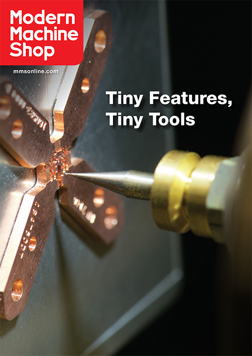
Challenge Machine specializes in micromachining of medical and semiconductor parts. Here, a 0.007-inch ball end mill is cutting features in a contact ground housing that is used for a semiconductor test application.
Challenge Machine se especializa en el micromecanizado de partes médicas y semiconductores. Aquí, un escariador de bola de 0.007 pulgadas está cortando características en una caja de puesta a tierra por contacto, usada en una aplicación de prueba de semiconductores.
Las máquinas tienen husillos de 100,000 rpm, pero el taller normalmente los opera a no más de 80,000 rpm.
Las máquinas 363-S usan un brazo de robot para cambiar automáticamente herramientas desde carruseles de 36 estaciones. Las herramientas para trabajos posteriores pueden alistarse en otros carruseles, lo cual le permite al taller cambiar fácilmente carruseles completos para cambiar más rápido la pieza de trabajo.
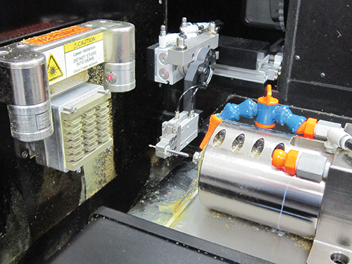
La sonda láser es usada para verificar fracturas de la herramienta durante trabajos de corrida larga.
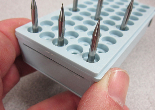
Para la mayoría del trabajo de microfresado, Challenge Machine usa escariadores de Performance Micro Tool. El taller ha usado de manera efectiva herramientas de sólo 0.001 pulgadas y el señor Betland dice que las mejoras en las geometrías y acabados de las microherramientas han sido clave para permitirle al taller obtener lo máximo de sus equipos de alta velocidad.
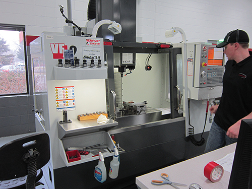
Parte del trabajo de micromecanizado se desarrolla en los dos VMC Haas VF-2 de 30,000 rpm que tiene el taller.
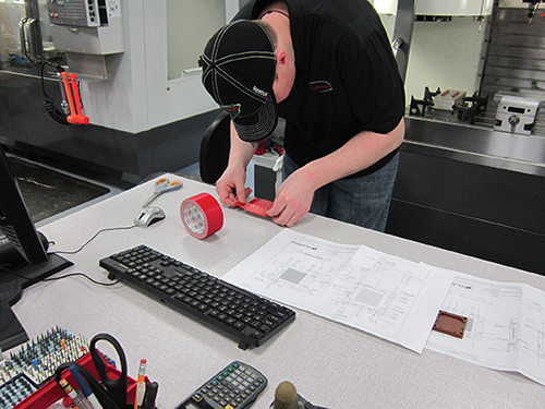
Debido a que mantener la planitud entre operaciones es crítico, el taller puede usar mesas de vacío o cinta de doble cara para asegurar las piezas para el mecanizado.
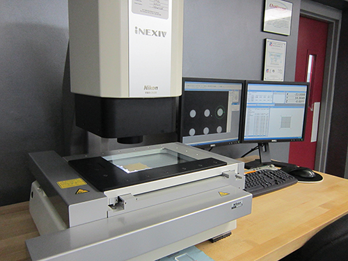
La inspección de partes y características pequeñas puede ser engañosa. El taller usa indicadores de gota con medidores de pasador para medir manualmente la altura y la profundidad de características como avellanados. También usa sus dos sistemas de visión Nikon para medir características automáticamente, por ejemplo, diámetros de agujeros.
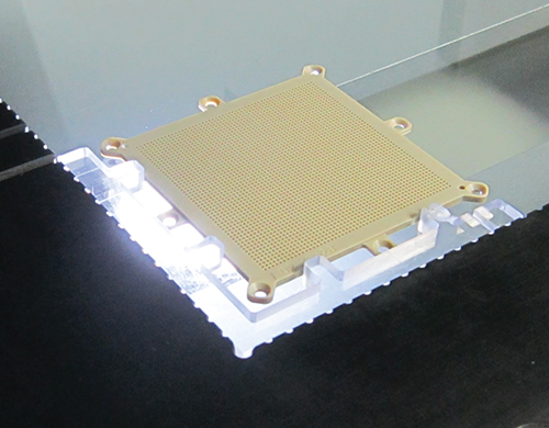
Esta pieza tiene 2.900 agujeros para medir.


Micromachining is becoming a bigger part of Challenge Machine’s business. Jim Betland, company CEO, says it currently represents 30 percent of the work this Blaine, Minnesota, job shop performs. In fact, that percentage is likely to increase with growing demand largely from the medical and semiconductor industries.
What’s interesting about Challenge Machine is the range of equipment—and available spindle speeds—this shop has added over the years to perform micromachining work. In fact, two of the shop’s machines have 100,000-rpm spindles, enabling them to effectively use end mills as small as 0.001 inch in diameter (one-third the diameter of a human hair).


During a recent visit, Mr. Betland explained how the shop’s micromachining capabilities have expanded and how it applies the lessons learned machining on a micro scale.
What’s Micromachining?
Prior to forming Challenge Machine, Mr. Betland worked for a manufacturer of semiconductor components that was looking to identify a more effective way to machine very small features in plastics. Lasers couldn’t deliver the necessary clean edges, and using spindle speeders with small cutters on low-rpm machine tools yielded limited success.
In 1999, he decided to go out on his own and focus on micromachining work, starting Challenge Machine in his garage. It was clear that design features on new semiconductor and medical parts were trending smaller, and there weren’t many shops in the area that could effectively machine such tiny features.
Mr. Betland started using a Haas VF-2 VMC with a 15,000-rpm spindle and began performing contract work, primarily micro-drilling and micro-slotting operations, for his previous employer. As the amount of work increased, he moved to a rented space and added a second 15,000-rpm machine. A couple of years ago, Challenge Machine moved to its third and current location in a 16,000-square-foot, environmentally controlled facility just north of Minneapolis.
Approximately 80 percent of this 18-person shop’s work involves machining prototypes and producing small batches of parts with micro features in both plastics (glass-filled, Ultem, Torlon, etc.) and metals (aluminum, copper, brass, stainless steel, etc.). Typical lot sizes range from a single piece to 10 pieces with lead times of just one to two weeks. Much of the plastics micromachining is performed to create prototypes that will eventually be molded during the production run. Not only does the shop apply its micro-milling capabilities for this work, it also uses Swiss-type lathes with live tooling and high-speed air spindles for prototyping and small-batch production of turned parts that often require some milling work.
So what’s micromachining? Everyone has a different definition, but Mr. Betland views it as machining with tools smaller than 0.015 inch in diameter and tolerances of just a few tenths. It takes significant spindle speed to effectively use such small-diameter tools, but he says that wasn’t really the issue early on. This machine provided the speed, but the challenge became finding cutting tools that offered the long life and repeatability that would enable the machine to run at high rpms.
Soon after purchasing that first machine, Mr. Betland began interfacing with micro-tool manufacturer Performance Micro Tool (PMT), which also started its business in 1999. Over the years, Challenge Machine has offered feedback to PMT with regard to how its end mills were performing, which was helpful as PMT continued to refine the design of its tools. This communication has helped the cutting tool supplier to create micro tools with improved geometries, runout and edge finish.
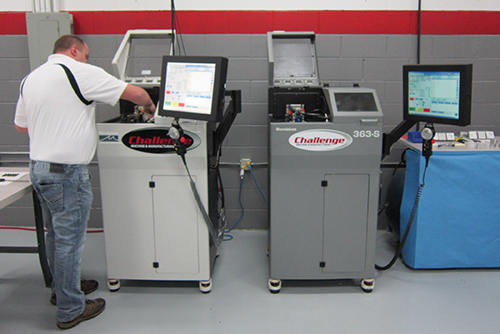
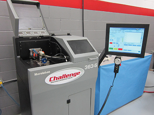
With micro-end-mill designs improving, the shop looked to add equipment with even higher spindle speeds. It brought in a 45,000-rpm Benchman benchtop CNC machine from Intelitek and followed that with the purchase of a Microlution 363-S horizontal CNC machine it discovered at IMTS. This machine is designed specifically for micromachining, having travels of just 2.48 inches in each of the three axes. Plus, it occupies roughly a 2-foot-by-2-foot area of floor space and stands 4.4 feet tall. In fact, the shop has since added a second 363-S machine that is installed next to the first one.
The 363-S features a ground natural granite base to damp vibrations. The machine uses a linear stage to precisely move the workpiece in the X-Y plane and a Z-axis stage for spindle motion. Linear motors enable it to surpass more than 2G acceleration while achieving 1-micron positional accuracy.
The 363-S line is available with a number of spindles and spindle speed options. Mr. Betland chose a 100,000-rpm ceramic hybrid ball bearing spindle that features an automatic, air-operated tool-changing collet. With this system, the tool shank (with a maximum diameter of 0.125 inch) installs directly into the spindle without a toolholder. This interesting design element helps the machine to achieve spindle runout of 2 microns.
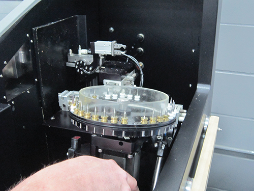
The machine’s 36-position tool carousel raises to present the proper tool to the machine’s tool-changing robot arm. This robot arm grips rings pressed onto each tool’s shank to deliver the tools between the spindle and carousel. The fourth photo to the left shows rings made from brass and Delrin. The shop has found that the newer-generation Delrin rings are easier to press on and off the cutters than the brass versions.
Tools for upcoming jobs can be set up on other carousels, enabling the shop to easily switch entire carousels for quicker job change-overs. A laser probe mounted on the X-Y stage above the workzone is used to check for tool breakage during long-running jobs. An Erowa MTS (modular tooling system) pallet system offers a defined zero-point location to enable repeatable positioning of workpiece pallets on the machine’s X-Y stage.
Micro Lessons
Mr. Betland says the tool paths the shop uses for micromachining aren’t much different than those used for conventional-sized work except that the stepovers are much smaller. For example, a typical stepover for a 0.001-inch end mill is 0.0003 inch. Feed rates for plastic workieces are generally higher than metals, although the spindle speeds are relatively the same.
The cutting parameters the shop uses for micromachining are largely based on experience and trial and error, and these have been firmed up thanks to improved consistency in cutting tools. That said, Challenge Machine will often examine new cutting tools smaller than 0.004 inch in diameter under a microscope, not to measure them, but simply to check for any irregularities prior to use.
Of course, the shop has picked up a few micromachining tricks over the years. One technique it sometimes uses to create square-edge micro-slots starts by using a ball end mill to essentially rough out the slot before coming back with a standard end mill to create the sharp corners. This minimizes the load on the standard end mill.
In addition, pecking cycles are used for some micro-drilling operations, and the pecking feed distance depends on the material and hole size. However, Challenge Machine has found that some applications lend themselves to drilling without pecking. This is often the case for polyetheretherketone (PEEK), requiring an adjustment of speeds and feeds to generate the proper chip size per tooth so chips can be evacuated out of the hole.
The shop also tries to integrate deburring operations during the machining cycle as much as possible to minimize manual deburring work. For parts that require a number of through-holes, simply plunging a drill completely through the part in one direction can create an exit burr that would need to be removed. Creating blind holes at each through-hole location during Op10 work serves to make a clean edge break for each hole on the back of the part. This prevents burrs from developing after the part is flipped for Op20 work and the through-holes are completed. Alternately, if face milling is required after holes are drilled, the shop might slowly run a drill backward down each hole to remove any burrs that milling created.
Challenge Machine also commonly provides micromachining lessons to its customers. For nearly every prototype project, the shop works closely with the customer to offer design-for-manufacturability (DFM) suggestions. For example, a part with a callout for a 0.001-inch tip radius would require the shop to use a 0.002-inch-diameter tool. If the designer can accept a 0.0015-inch tip radius, then the shop can use a cutter with a 0.003-inch diameter to speed the machining process.
When Bigger is Better
Depending on the application, and the amount of micromachining a part requires, the shop’s 15,000-rpm Haas VMCs can use tools as small as 0.005 inch in diameter. These machines are largely used for micro-drilling work and some slotting operations. However, the shop has recently added two 30,000-rpm Haas VF-2 models that can use tools with diameters as small as 0.003 inch. They serve as helpful complements to the 363-S machines.
Small parts with micro features are good candidates for complete machining on the 363-S machines. However, other parts that require some micromachining can be relatively big (say, the size of your fist). These parts might be completely machined on the VF-2s if just a limited amount of micromachining is required. However, if a big part requires a significant amount of micromachining, the shop will often rough the conventionally sized features on one of the VF-2s for faster material removal, and then complete fine slots and other details on a 363-S. In fact, the shop is in the early stages of adding the same Erowa pallet system used on the 363-S machines to the Haas equipment. Not only will this speed setups when pallets are moved between machine platforms, but it will also enable the shop to more easily remove/reinstall a part on the VF-2s to simplify in-process inspection.
Micro Inspection
There are a number of microscopes throughout Challenge Machine to enable operators to inspect tiny part features or tools. For many parts, final part inspection in the quality department commonly combines manual and automatic measurement processes. Drop indicators with pin gages are used to manually determine part height or the depths of features such as counterbores. This can be challenging for parts such as the one shown to the left, which calls for a counterbore depth with a tolerance of +0.025/-0 mm for 2,900 holes. Next for this part, one of the shop’s two Nikon InexIV VMA 2520 vision systems automatically measures the diameter of every hole. These compact benchtop vision systems have 250 by 200 by 200 mm measuring tables, which are plenty big enough for the type of work Challenge Machine performs.
The attention to detail in the manual inspection points to a significant problem the shop faces: finding new shopfloor employees. Mr. Betland says that although this is difficult for all shops, it is particularly problematic for Challenge Machine. It’s tricky enough teaching prospects how to run a conventional-sized machine, but that is magnified when you also have to get them comfortable using cutting tools one-third the diameter of a human hair and microscopes for deburring, and proficient in all the other skills needed to produce small parts with finely machined details.


Related Content

Grob Robot Cell Enables Long Periods of Unmanned Operation
The GRC-R12 robot cell features a pneumatic single- or double-gripper system, as well as a drawer feed system with six drawers.
Read More
Horizontal Turning Center Ready for High Production
Romi Machine Tools’ new GL300 S features high-power torque and feed force and is built with a robust monoblock base for ultimate rigidity and precision.
Read More
Translating a Prototyping Mindset to Production
The experimental mindset that benefited BDE Manufacturing Technologies as a prototype job shop has given it an adaptable edge as a production facility.
Read More
The Job Shop Is the First Half of the Business
By day, NTL Industries went from a lathe and a mill in a home garage to an 11-employee enterprise in under five years. By night, it tackles a new future.
Read MoreRead Next


3 Mistakes That Cause CNC Programs to Fail
Despite enhancements to manufacturing technology, there are still issues today that can cause programs to fail. These failures can cause lost time, scrapped parts, damaged machines and even injured operators.
Read More
The Cut Scene: The Finer Details of Large-Format Machining
Small details and features can have an outsized impact on large parts, such as Barbco’s collapsible utility drill head.
Read More