
Modern CNC Control Systems for High Speed Machining
All around the world, companies that machine molds and dies face numerous challenges as well as numerous opportunities. How these companies are responding are influencing the entire metalworking industry.


full scale automobile models
High Speed Cutting Process
A high speed cutting system consists of of different components like machine, spindle, CNC control etc.
Although there have been significant improvements in those components, further progress still has to be made. Especially life time of spindles, secure clamping of tools and the cutting life time of tools are to be improved.


For the high speed machining process, also CAD/CAM systems are very important. If using 3D CAD/CAM system in conjunction with modern high speed machine tools and controls, a saving of about 40% in time of the whole process can be achieved.
Before discussing the specific CNC functions required for high speed machining, we will give some examples of applications where high speed machining has been put into practice.
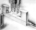
Application example: High Speed Cutting in model construction
The newest generation of high speed machining centres provides ways of considerably accelerating vehicle development. This is particularly true of body work modelling during the development stage. The milling of full-scale models, which do not need to be smoothed or reworked in any way before being painted, can nowa-days be produced economically and within reasonable time scales using HSC technology.
A requirement is that everything is available in CAD format, e.g. the body surfaces with fully described data surfaces. Data from a variety of CAD systems can be used.
The five axis high speed machining centre situated in the prototype centre of a user of Siemens control technology is able to machine workpieces up to 2200 x 1100 x 4500 mm in size and is therefore also used to produce full scale automobile models.
The surface quality of a full scale model (data control model) machined using modern milling techniques is so high that no milling marks can be seen and the workpiece can be painted immediatly with out reworking. The painted surfaces can be silvered. This RDP process (RDP = rapid design process) has proved itself in a large number of projects.
The argument is often put forward that people want to retain their existing milling strategy in order to save time and money and then polish the surface by hand. The problem with this is that manual intervention can never be 100% accurate and that time is lost and the potential for error increases through the repeated treatment of the surfaces.
The data associated with the digital product model is used in the RDP process, as all changes are implemented directly in the CAD system. This provides absolute certainty that the data record will correspond exactly to the prtotype when the model is released. This ensures that the correct data record, including all modifications, is used during tool manufacture. Modification costs and time lost during tool manufacture are minimised. This process will not render the clay model during body design superfluous. The classical cubing operation (with manual changes and the feedback of data) is now a thing of the past, having been replaced by milled 1:1 data control models, as the transparency of the data is seen as a significant advantage in terms of saving time and process accuracy.
Application example: blade manufacture
The designers of turbine blades are making a significant contribution to the continued improvements in efficiency. Improvements in arrangement, rigidity and geometry are leading to an efficiency revolution in fossil fuel fired power stations. The designers are coming up with new ideas for the blade profile that reduce the undesirable effects of the secondary turbulence of the steam.
Blades that have been fine tuned with respect to flow (so called 3D blades) have resulted in a 2% increase in energy output (efficiency) in Siemens steam driven power stations. In the case of a 700 MW steam driven power station this represents an additional 30 million Kilowatt howers of electricity without discharging a single kilogram more carbon dioxide into the atmosphere.
The Power Generation division of Siemens uses HSC technology and 5-axis milling machines in its factories in Mülheim an der Ruhr and Görlitz for the machining of complex blade profiles. As tens of thousands of these blades are manufactured each year, the time spent on each one needs to be optimised. As far as possible, the blades need to be ready to be installed as soon as they come off the milling machine. Manual reworking is more or less eliminated, as modern CNC controls utilising highly accurate, digital control processes with no lag error produce a top quality surface finish (residual roughness, accurate geometry).
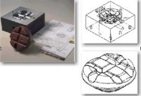
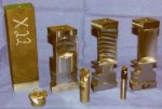
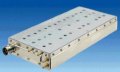
Application example: HSC hard milling of tool inserts
A requirement for the economical manufacture of thermoplastic parts is to have a high number of picks in the injection moulding machine. This requires that specially hardened tool steel is used in the manufacture of tool inserts.
The die used in the manufacture of an insulator component (terminal insulator for catenary wire of tram overhead system) was HSC milled directly from hardened steel (HRC 52).
The advantages of hard milling compared to erosion of the material using copper or graphite electrodes are shorter manufacturing and throughput times and improved quality as a result of the elimination of distortion due to hardening.
In the example, it was possible to reduce the overall manufacturing time to 8 hours from the 51 hours required by the previously employed erosion method. The residual roughness figures of Ra = 0.5 to 0.7 µm are so low that the tool does not have to be polished.
HSC hard milling does however require special tools and milling strategies that take account of the requirements it imposes. In particular, the extreme machining requirements and the desired geometrical accuracy of + 0.02 mm and residual roughness of Ra <0.7 µm necessiate a powerful drive and control system, which must be able to deliver the appropriate degree of contour accuracy and control quality under harsh conditions.
As a result of its simpler machining requirements, HSC technology can also be used to good effect in the manufacture of electrodes, the use of which cannot be avoided in the case of highly detailed tools.
CNC control technologies for HSC machining
Interpolation method
The linear interpolation method that is predominantly used in modern CNC controls causes a whole range of problems in the manufacture of workpieces with freeform surfaces.
Firstly, the mathematical representation of CAD/CAM systems is fundamentally different from the use of straight sections to define a simple path for the CNC.
To define curves and surfaces, CAD/CAM systems employ spline algorithms, or more precisely NURBS (Non Uniform Rational B Splines). NURBS enable both freeform curves and conics (straights, circles, ellipses, etc.) to be defined in a uniform manner.
This way of representing curves and surfaces has been adopted in the STEP standard (Standard for the Exchange of Product Model Data, ISO/IEC 10303).
To generate linear blocks, conventional CNCs therefore have to approximate the highly accurate surface representation. As a high degree of geometrical fidelity is expected, a low chord error must be selected in the approximation, which will make the NC programs very large and therefore result in long transmission times. Part programs of several tens of MBs in size are normal.
Block cycle time and other problems with linear interpolation
A CNC control works on a cyclic basis (block cycle time T, typically 1 to 10 ms). The following relation exists between the average length of path I of a block (in mm), the block cycle time T (in ms) and the maximum possible feed Fmax (in m/min):
Fmax = Length/CycleTime *60
For example, in the case of a path with a Length of 10 µm (=0.01 mm) and a block cycle time of 2 ms, the maximum feed Fmax is limited to 0.3 m/min.
The short linear blocks that were selected for quality reasons therefore not only generate large amounts of data but also limit the maximum possible feed ("block cycle time problem"), which conflicts directly with the required high HSC path feed requirements.
A series of linear blocks is represented by a polygon with corners. If this polygon is to be machined accurately, a large axial acceleration will be generated when moving from one block to the next. This would theoretically necessitate an acceleration that was infinitely large.
The control must therefore ensure that the dynamics of the individual axes are not exceeded (maximum permitted limiting acceleration of the individual machine tool axes). This can only be achieved by greatly reducing the tool path feedrate around the corners, which has a knock on effect on machine productivity.
When used in conjunction with control systems that have no lag, these acceleration jumps also induce vibration in the machine tool and are responsible for extremely high stressing of the machine axes.
Linear blocks take the form of facets as well as vibration patterns on the workpiece.
Spline interpolation
Interpolation methods that employ spline blocks (NURBS blocks) provide a way out. Experience shows that a spline block can replace between 5 and 10 linear blocks without sacrificing accuracy. Spline interpolation eliminates the previously necessary approximation of smooth workpiece surfaces by thousands and thousands of small linear blocks.
The polygon programming performed earlier is therefore replaced by either transferring spline blocks directly from the CAM systems or through a CNC internal geometric conversion (compression of linear blocks).
An example of such spline blocks is shown in the following extract from a part program.
N29 PO[X]=(-3.525,.001) PO[Y]=(20,-.014,.006)
N30 PO[X]=(-33,-26.371,26.155) PO[Y]=(20,6.947,-3.367) PO[Z]=(23.977,25.953,-25.953)
N31 PO[X]=(-33,.265,.095) PO[Y]=(20,-.034,.012) PO[Z]=(20.977,-.847,.489)
"PO[X]" stands for "Polynomial for the X axis"
The data is standardised in such a way that the block end position is shown right after the open bracket in the same way as a linear block.
The coefficients of a third degree polynomial are passed for each axis, for example the X axis:
x(t) = a · t3 + b · t2 + c · t + d
Design of Modern CNC Systems
The architecture of modern control systems is based around digital signal processing and the use of a bus to connect the various components. Highly integrated electronic circuits (ASICs) are used, enabling the size of the control to be minimised.
The CNC consists of the following main components:
- Operator panel based on industry-compatible PC technology for the man/machine interface (MMI)
- CNC control unit (NCU)
- Programmable controller (PLC)
- Drive modules for machine tool axes and spindles (feed drives VSA, and main spindle drive HSA)
- Motors (AC motors and linear drives)
- Supply and energy recovery unit (S/E unit)
As each drive module, the NCU, the PLC and the operator's panel each contain a processor, a modern CNC can also be seen as a multiprocessor system.
Digital drive technology
One of the most important functions in high speed machining is the precise guidance of the feed drives and spindles. The traditional analog connection between CNC and analog drives has been replaced by digital drives, which are connected to the CNC dvia the digital high speed bus.
Digital control technology is used in both the drive module processors as well as the CNC to control position, speed and torque of the motor. Measuring systems report the actual position of the axes very accurately.
Productivity and tool accuracy is increased through complex control algorithms that minimise contour errors and machine rigidity problems such as torque damping, speed and torque feedforward control.
The digital drive control supports the following functions:
- High resolution digital speed and path monitoring
- Higher order control algorithms, in particular compensation of the lag induced contour error through speed and torque feed forward control (important in the case of high tool path feedrates and the resulting error)
- Wide range of analysis options, e.g. measurement of frequency response
- Automatic circular test with automatic optimisation of the reversing error that occurs at axis reversal points (quadrant error) using neural networks
Connection of direct drives, e.g. linear motors - Machine safety functions implemented across two channels using CNC and drive processors
CNC functions for HSC machining
The required degree of accuracy at high tool path feedrates can only be achieved by using control strategies that eliminate contour error. Furthermore, as the traditional Kv value (usually Kv = 1 to 4) provides no damping, the interpolative guidance of the axes becomes extremely important.
New ideas regarding path interpolation, feed rate control and five axis transformation are required in order to satisfy the special demands imposed by high speed machining.
Higher order interpolation methods for precise path definition and rapid interpolation have already been discussed.
The HSC CNC machine must also satisfy the following requirements:
- Look ahead feedrate control over more than 100 blocks
- Transformations, e.g. for clamping corrections or 5-axis transformation
- Elimination of contour error in the axes to provide greater path accuracy
- Torque damping along the feed path and in an axial direction to reduce machine wear
- Tool correction (length, radius, various types of cutter)
- Automatic path smoothing functions for smooth surfaces
- Compensation for mechanically induced errors
- Safe operation of the machine in the work area
Look ahead feedrate control
The task of the look ahead function is to identify irregular (in terms of feedrate) block transitions and excessive axis acceleration caused by path curvature. A requirement for the continuous processing of NC blocks whose execution time is shorter than the ramp up and down times demanded by the machining speed is a program buffer that can be monitored in advance.
It should be noted that the required look ahead distance could extend to 50 - 150 blocks if lower rates of acceleration occur in conjunction with high feedrates for technical reasons. If the available look ahead buffer is small, the feedrate must be restricted so that the braking ramp can be stopped at any point in the program.
Five axis machining
Five axis machining in a rotated coordination system (e.g. five axis machining on inclined surfaces) can often only be achieved using programs that have been produced offline.
In addition, the tool type, radius and length are declared as constants in the CNC program, which makes modifications to the program and tool on the machine tool itself extremely difficult.
Internal transformations within the CNC provide a solution to this problem. These enable a certain amount of programming and tool correction to be carried out directly on the machine without having to repeat the post processing procedure.
Instead of programming in machine coordinates and machine axes, a new work piecespecific coordinate system can be defined (e.g. for inclined surfaces). The CNC handles the conversion of the work piece coordinates into the appropriate axis coordinates.
Tool orientation can be programmed via rotary axis positions, tool direction vectors, RPY angles (RPY = Roll/Pitch/Yaw) or Euler angles.
This function is also important when in manual mode, e.g. free travel in the case of a tool break.
Five axis transformation
Three axis machining using ball cutters only utilises a fraction of the potential productivity of a 5-axis milling machine. It is only when cylindrical or toroidal tools are used that cutting performance reaches acceptable levels. These cutters have to be oriented with the cutting path in a defined way in order to achieve the maximum cutting performance along a contour, while at the same time ensuring that the surface quality is of a high enough standard.
To ensure the tool travels along the desired path, conventional 5-axis programming of the tool on rotary axes requires the insertion of numerous intermediate cuts.
Five axis transformation ensures that the tool tip remains stable by dynamically adjusting the angle of advance using the hand held control unit (RTCP function for "3+2" axis operation).The programmed feed then corresponds to the path of the tool tip.
As the CNC can correct the tool length, it is possible to measure the tool directly on the machine during the machining process, to react accordingly in the event of tool breaks and to compensate for tool wear automatically by correcting the CNC as necessary.
These functions enable the machines to run unsupervised during the night. The CNC provides appropriate measuring cycles that perform tool setting and break monitoring automatically in conjunction with laser systems.
In addition, the correction of various kinds of cutter geometry, such as cylindrical, toroidal and conicaltoroidal tools, takes place within the area that is currently being machined by the CNC, so that different tools can be used for the same program.
Compensation
To keep the costs for the machine tool builder within limits, the CNC must compensate for static, dynamic and temperature related machine errors7. This enables tool accuracies to be achieved that were earlier only possible by spending large amounts of money on various mechanical components. Particularly important compensations for HSC applications include:
- Compensation for temperature induced errors caused by high spindle speeds and axis feedrates through heating of the spindle and feed axes
- Compensation for friction errors at axis reversal points (quadrant errors)
- Compensation for leadscrew errors and errors in measuring system
- Compensation for angular and sag errors in machine tool through interpolative compensation (volumetric compensation or cross error compensation)
- Compensation for play in axes that are not measured directly
Linear motors are increasingly being used in machine tools
Drive technology in machine tools is nowadays dominated by rotary servo motors in conjunction with ball screw, gear racks or toothed belts. Whereas in the past the electrical drive was the limiting factor in terms of acceleration and traversing speed, it is now the mechanical transmission elements that are imposing the restrictions. New performance potential is being realised through the use of linear motors and specially designed mechanical components together with powerful NC controls.
Despite extensive fine tuning, ball screw spindle drives cannot exceed 6m in length and a velocity of 1m/s. Non linear influences in the control system, such as mechanical play, backlash on reversal and inertia, affect accuracy and machining speed. A machine tool that is supposed to operate outside these limits must be free of such influences. As the mechanical transmission elements have the sole function of converting a rotary movement into a linear one, the future points towards linear direct drives. Direct drives require no conversion and can be installed wherever the power is required.
A linear motor consists of a primary element, which contains the motor winding, and a secondary element that extends over the entire distance to be traversed. Together with the linear guides and the linear measuring system of the NC machine, this active element forms the linear direct drive itself.
In a similar way to rotary motors, linear motors can also be differentiated by their different modes of operation and design. In the case of machine tools, the most widely used types of motor are single stator ones. In these motors a solitary primary element moves over a secondary element. In situations where traversing distances are short, this principle can also be reversed. This results in low moving masses, which allows highly dynamic applications, such as out of roundness, to be performed. Another version is the dual stator motor, in which the secondary element is acted on by two primary elements. This doubles the amount of feed, while the magnetic forces between the primary and secondary elements are more or less equalised.
The question whether to employ synchronous or asynchronous operation has already been decided in the case of rotary motors. The disadvantages associated with synchronous operation, such as permanent attraction and expensive secondary elements, are more than compensated for by a whole raft of benefits, including simpler control structures, smaller power sections, lower weight and volume, more power, together with more accurate positioning and less heat generation. These features are extremely important in the case of machine tools although to achieve best results, additional measures have to be implemented. For example, the concept of "heat generation" is relative if one considers that the "linear motor" heat source is located in the heart of the machine tool. The linear motors must therefore be thermally isolated in order to achieve machining accuracy down to micrometer level when using direct drive technology.
Assuming that the aim in the case of rotary drives is to pass the generated heat to the housing as directly as possible so it can then be dissipated by the coolant (air, water), the situation with linear motors is different: the Siemens 1FN linear motors are based on the thermosandwich principle. The heat source in the motor is thermally isolated from its surroundings. The motor is prevented from overheating by a water cooler in the primary element. To ensure the thermally sensitive area around the mounting is at more or less the same temperature as the motor, a low power precision cooler is also integrated. This construction restricts the temperature rise around the mounting to no more than 2 Kelvin above the water inlet temperature, which in turn enables precision work to be carried out. There is one precondition that applies to every application, irrespective of whether it is ultra high precision machining, high speed cutting or handling: both open loop and closed loop applications must be able to use these newly acquired technologies. What use is it to the user if the machine processes a workpiece four times faster than before but the contour accuracy deteriorates by the same factor? The objective must therefore be to machine significantly faster while retaining or even improving contour accuracy. This imposes a considerable performance requirement on the NC and the drive control.
For example, the power trains of electromechanical drives exhibit several degrees of elasticity, which means that the mechanism must be described as an oscillating multimass system. This causes the mechanical transmission elements on the one hand to limit the dynamics and the gain factor Kv and on the other to impart a mechanical rigidity that damps the effect of sudden load changes. As linear drives have no mechanical rigidity, this task has to be performed by the electronic drive control. A linear drive controller must therefore be extremely fast and employ sophisticated filter technology. The filters prevent mechanical resonance of the machine tool when the motors are under highly dynamic control.
Accelerations of 2 g, rapid traverse velocities of 120 m/min and position controller gain factors of Kv = 30 µm/mm/min can be achieved in machining centres by using this technology in conjunction with the Sinumerik 840D/Simodrive 611D control and converter system. In the case of axes used for out-of-roundness machining, accelerations of up to 45 g can be achieved with dual stator motors and moving secondary sections.
In addition to machining results, machine availability is also a major factor. The mechanical design of the motor has a significant impact in this area. Because of where they are installed, the motors must be robust, have a high degree of protection against environmental influences and be easy to install. With its linear motors, one has to therefore place considerable emphasis on reliability and ease of service. The motors are hermetically encapsulated in a metal housing to IP65. All motor windings are monitored using temperature sensors and protected against overheating. Commissioning and diagnosis of the linear drive motors is supported by intelligent software packages.
Safety for operator, machine and workpiece
The health and safety regulations in force nowadays stipulate encapsulation of the working area for practically all types of machine tool. This is to prevent the operator intervening in the programming or machining process. A qualified assessment of the situation by the operator or machine tool setter and implementation of any necessary corrections (e.g. modification of the angle of advance) during automatic program processing is very important, especially in the case of the large machine tools used in moulding and tool manufacture.
For safety reasons, this requirement can only be satisfied through extensive protection and monitoring systems. These systems will include the monitoring of all machine functions by the PLC.
More far reaching measures ensure the safe two-channel control of spindle speeds and axis movements. Such measures also satisfy the requirements of international legislation (requirements of safety category 3 of prEN954-1 and the EU Machinery Directive 89/392/EWG) and any internal company regulations.


Related Content

YCM Alliance Hits IMTS
YCM Technology has joined with other like-minded machine tool manufacturers to take a solutions-based approach to manufacturing.
Read More
How to Accelerate Robotic Deburring & Automated Material Removal
Pairing automation with air-driven motors that push cutting tool speeds up to 65,000 RPM with no duty cycle can dramatically improve throughput and improve finishing.
Read MoreRead Next

3 Mistakes That Cause CNC Programs to Fail
Despite enhancements to manufacturing technology, there are still issues today that can cause programs to fail. These failures can cause lost time, scrapped parts, damaged machines and even injured operators.
Read More

The Cut Scene: The Finer Details of Large-Format Machining
Small details and features can have an outsized impact on large parts, such as Barbco’s collapsible utility drill head.
Read More