
Retrofit Increases Productivity And Reduces Capital Outlay
Monitor Aerospace Corporation of Amityville is a producer of aerospace structural components for companies such as The Boeing Company. The company invested heavily in the 1970s in large expensive machinery, but more than 20 years later these aging machines were no longer keeping up with productivity demands.


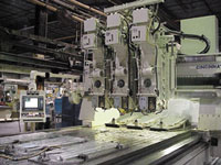
Adding current control technology has breathed new life into Monitor's older machine tools.
Monitor Aerospace Corporation of Amityville, New York, is a producer of aerospace structural components for companies such as The Boeing Company. The company invested heavily in the 1970s in large expensive machinery, but more than 20 years later these aging machines were no longer keeping up with productivity demands. The older controls on these machines had limited functionality, and operators had to continuously tweak the machines to compensate for wear. Moreover, maintenance costs were soaring and downtime was increasing.
Gary Kahrau, director of manufacturing engineering, and Chris Nagowski, facilities manager, had a dilemma. They needed to address the machines’ performance problems, but they did not have access to the enormous capital outlay necessary to replace them. Mechanically the machines were in fairly good condition, so they decided to explore retrofitting the machines with new controls as a solution to their problem. They knew that new controls would provide more flexible functionality, higher reliability and less downtime, but they also hoped that newer error compensation capabilities would help make up for some of the machines’ wear related tolerance problems.


As Mr. Kahrau and Mr. Nagowski explored their retrofit options, their first task was to decide on a control. They wanted a control that would give them ease-of-use, high reliability, and sophisticated capabilities such as five-axis movements and advanced error compensation. Just as importantly, however, they wanted an open control that they could integrate into their existing plant system architecture and that would be poised for integration with undefined systems of the future.
Traditional controls offered the motion and compensation sophistication they were looking for but did not offer the flexibility and integration capabilities they wanted. On the other hand, purely PC-based controls, which offered the integration and operator flexibility they wanted, did not offer the motion sophistication they needed.
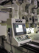
As their search went on, Mr. Kahrau and Mr. Nagowski spoke with CNC Engineering, Inc. (Enfield, Connecticut) and learned about CNC Engineering’s PC-based Open Vision HMI system for the GE Fanuc series of controls. This system provides a hybrid solution that ties together a flexible and powerful PC-based front-end with the motion and compensation capabilities of a GE Fanuc control. Based on GE Fanuc’s HSSB, and using an industrial PC for the operator interface, Open Vision HMI provides access to all of the control’s native functions through intuitive touch screen menus. And, since the operator interface is on a PC running Windows NT, custom screens and options are readily available, and advanced network and system connectivity is fully supported.
The first machine Monitor decided to retrofit was a three-axis Cincinnati Bridgemill. This was a sound machine, but the X-axis gearboxes were worn, and the machine was not holding tolerances well. Rebuilding the gearboxes would be an expensive undertaking, and Mr. Kahrau and Mr. Nagowski thought that this expense could be avoided by applying some of the advanced error compensation functions available in a newer control. Working with CNC Engineering, a specification was developed for the control. For this application, Monitor decided to use a GE Fanuc 15MB control with CNC Engineering’s standard Open Vision HMI Software. (The front-end software would run under Windows NT Workstation, and the PC initially would be connected to Monitor’s Local Area Network via a standard Ethernet topography.) Since the GE Fanuc control had many options that might help compensate for the worn gear boxes, it was decided to add compensation features one at a time and perform accuracy tests after each feature was implemented to quantify the results.
Monitor has tight production schedules, and it could not spare the machine for the protracted period of time associated with a full in-field retrofit. CNC Engineering’s CPR (Certified Pre-assembled Retrofit) package solved this problem. Under the CPR program, engineering and design specifications were worked out in advance during an initial site visit. During the site visit, detailed measurements were taken of the machine, and new component placement was finalized. The engineers at CNC Engineering spent considerable time working with Monitor to specify the optimum operators’ pendant for the application. In this case, the original operator console was removed, freeing up a large amount of floor space, and a new three joint operator pendant was designed for maximum operator convenience. With the information from the site visit the entire retrofit package was engineered, designed and assembled at CNC Engineering’s facility. During the engineering and assembly phase all necessary electrical schematics, cable lists, panel layouts, mechanical prints and ladder programs were developed. The exact equipment that was to be installed at Monitor was then assembled, wired and powered up. All parameters were loaded into the control, and the entire package was then tested exactly as it would be on the machine—right down to servomotors with their custom length servo cables. Once testing was finalized, the package was shipped to Monitor for field installation. For this machine the installation took 3 weeks.
When the new control was in place, it was time to test the impact of various error compensation capabilities. Laser measuring was performed along each axis. The results of the laser measurements were input into the Pitch Error Compensation Tables, and a circle-diamond-square test was performed. This test part was compared to a previous test part cut before the retrofit was done. The comparison showed a significant improvement in accuracy as well as finish. After analyzing the laser results for the X axis, a definite cyclic error, every 0.750 inch, could be seen—probably the result of worn gears in the gearboxes. The cyclic compensation function was added, the proper parameters were set, the machine was re-lasered, and a circle diamond square was cut. Again further improvement was made. The wear in the rack and pinions of the X axis was also contributing to bi-directional errors. By implementing bi-directional error compensation, further improvements were once again realized. With these three compensation options applied, Monitor was able to avoid the expense of dual gearbox rebuilds while improving part quality and increasing productivity.


Read Next

The Cut Scene: The Finer Details of Large-Format Machining
Small details and features can have an outsized impact on large parts, such as Barbco’s collapsible utility drill head.
Read More
3 Mistakes That Cause CNC Programs to Fail
Despite enhancements to manufacturing technology, there are still issues today that can cause programs to fail. These failures can cause lost time, scrapped parts, damaged machines and even injured operators.
Read More