
Speeding Up Splines
Moving small- to medium-batch production from outsourced, dedicated hobbing operations to in-house, CNC multitasking machines helps job shops achieve quick turnarounds and flexibility in supplying splines for the heavy-vehicle industry. Inserted disc cutters make this transition possible.
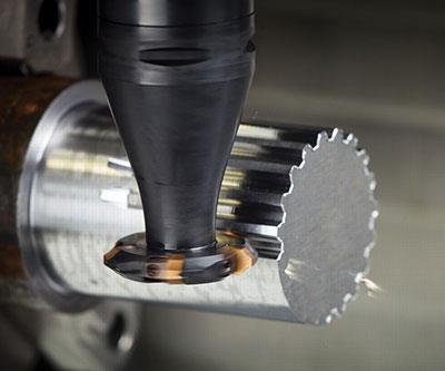
Milling with disc cutters fitted with indexable inserts is a flexible approach that enables a shop to machine splines without a large inventory of specialized hobbing tools on hand.
Disc cutters of different sizes can be used on CNC machining centers and multitasking machines to complete transmission components for trucks and other heavy vehicles in one setup.
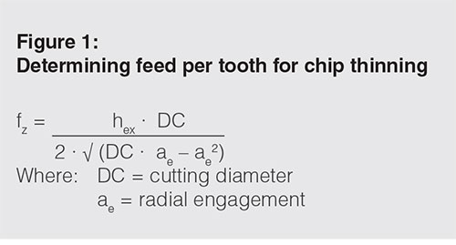
Chip thickness (hex) is crucial in determining feed per tooth (fz), which ultimately provides an optimal table feed.

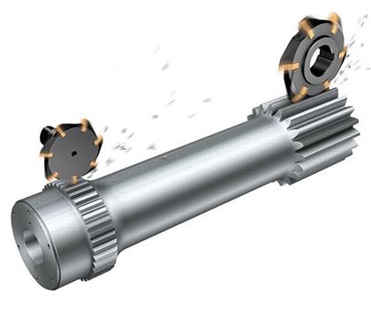
Different disc cutter styles are available for various spline applications and different spindle interfaces. Whatever style cutter body is chosen, the ability to swap out different indexable insert profiles on a single cutter body enables it to achieve different depths, root configurations and tip chamfers.

Adjusting for tool deflection.


By Aaron Habeck, Marketing Project Manager, Sandvik Coromant
Splines are often lost in the greater gear discussion. However, much of the same rotational geometry that goes into complex gear machining also applies to spline production. Given how commonplace splines are in heavy vehicles, mining, construction, agriculture and other massive, earthmoving-types of machinery, it’s a wonder they don’t get first billing as often as they ought to. A spline is involved practically anytime rotary motion needs to be transmitted from one shaft to another.


Given the load requirements of, say, axle splines in heavy machinery, increasingly complex splines—spline shafts with more teeth at different geometries—are required to maximize the contact surface area, and evenly distribute heavy loads from male to female splines.
OEMs and their Tier-One suppliers are asking for high-quality components from job shops and other producers. This isn’t especially new; component suppliers have long had the technology to produce splines that are ready for heavy-vehicle applications. As for meeting productivity needs with huge batch sizes, traditional high speed steel (HSS) tools, such as spline rolling racks, hobs, broaches and shaving cutters, have done the job admirably.
However, there is a push for increased flexibility. The pace of change has increased, and new model launches, often based on entirely new platforms, are more frequent than ever. Unfortunately, history shows that it has been difficult for spline manufacturers to react quickly to frequent
design changes.
An Intrinsic Drawback
For every suite of spline cutting depth, configuration and geometry, there’s a single HSS hob, broach or rack designed almost exclusively for that job. For long runs in a single batch, these processes serve quite well, producing highly repeatable results to tight specifications.
The drawback has been the need for redundancy in such hobs, as regular maintenance such as regrinding and recoating takes them away from the machine or out of the shop. To keep chips flying on a spline operation, shops historically had to have at least two of each individual HSS tool in inventory at any given time in order to accommodate scheduled regrinding/recoating or recover from possible failure.
As the pace of change increased in heavy construction equipment, the only way to remain flexible enough to handle spec or design changes, as well as to make prototypes, was
to own a complete set of hobs of all shapes and sizes to cover any contingency. Likewise, in production situations, owning two of each tool was prudent. For years, this has kept a lot
of the spline and gear work in specialized, dedicated shops.
Smaller Batch Flexibility
A leap forward on the flexibility continuum is happening now, because multi-axis and multitasking machines enable disc cutters to perform operations given exclusively to hobs, broaches, spline rolling racks and other tools in the past. Gashing or disc milling external or internal spline teeth can now be an extremely economical way to approach splines.
With multitasking machines and new insert developments, it is possible to have a single cutting tool accomplish several operations. This is especially crucial for small- to medium-batch production, which often requires frequent changes throughout the machining and handling process. Instead of producing 10,000 identical components to gain efficiency and economy of scale, shops can be capable of producing 100 of one type of spline, then 200 of another, without long delays or excessive difficulty.
The key is to exploit the flexibility of a disc cutter such as the CoroMill 172 from Sandvik Coromant. Using a disc cutter takes advantage of the adaptability of a multitasking machine and other non-dedicated types of machine tools. However, the inserts for the cutter are dedicated to a given spline size and tooth count. The user is then trading the flexibility of having a full inventory of hobs for flexibility inherent in machine design, whether it be a multitasking machine, a lathe with driven tools and a Y axis, or a machining center with a rotary table.
For example, instead of having a machine for the turning process and a hobbing machine for generating the spline, a multitasking machine can make the complete part. Another possibility is a cell that integrates a turning machine with a three-axis machining center equipped with a rotary table.
The benefits of machining the part complete in one machine are reduced setup times and improved feature-to-feature tolerances. By using a machining center and rotary table, the user is not locked into a dedicated machine. The machining center could be used for other components between setups for parts with splines. In addition, other features could be machined such as slots, cross holes, flats and more.
This flexibility has enabled many shops or Tier-Two suppliers to keep more jobs in-house. Spline operations that had been subcontracted to gear specialists can now stay in the shop—all that’s needed is a basic three-axis machining center and rotary table with a relatively small array of disc cutters with indexable inserts. One main advantage of these cutters is the ability to swap out different indexable insert profiles on a single cutter body to achieve different whole depths, root configurations or tip chamfers.
Compare that to the necessity of a single hob, spline rack or broach tool with the size and profile suitable only for a single job. Moreover, disc cutters (especially the kind that accept inserts that can be applied to a specific tool body) are inexpensive compared to hobs, spline racks or broaches. When the need for fewer tools and their ability to machine different kinds of splines are taken together, disc cutters shine as a truly economical choice.
Another factor to consider is setup time reduction. For many axle makers, every shaft features a small spline. If a shaft has to move from machine to machine for multiple operations, setup time adds up. The potential for human error in clamping, transporting and re-clamping also goes up. On multitasking machines with disc cutters, these splined shafts can be machined in a single setup.
Today’s manufacturers are looking for easier component handling with smarter, simpler and more flexible solutions. Repurposable disc cutters and flexible machines are one way to limit tool inventory and control costs for reconditioning, while simplifying workflow and eliminating maintenance headaches.
The Chip-Thinning Principle at Work
Chip-thinning calculations are essential in effective spline cutting when using disc cutters, as chip thinning is the most basic principle at work in the operation. The two primary feed recommendations from disc cutter manufacturers are usually programmed feed per tooth (fz) and maximum chip thickness (hex). Both of these values should be equal when a cutter is set to a radial cut engagement that is equal to or greater than its own radius. However, the desired chip-thinning effect can only begin to occur when the radial engagement is smaller than
the radius.
With disc cutters acting basically as gashing or slotting tools in spline manufacture, the small radial engagement in splines compared to the diameter of the cutter means that chip thinning should always take place. In order to get the best possible hex and optimize a spline “slotting” application, operators must calculate the value of fz, which is derived from disc cutter engagement as related to disc cutter diameter. Consider the formula for chip thinning shown in Figure 1.
If an operator fails to solve for the optimal feed per tooth, there’s a chance that the feed rate will be too low for the edge preparation or insert geometry. Because the tool body will provide some tolerance in runout, operators are generally advised to avoid going smaller than 0.003 inch (0.076 mm) in hex as a rule of thumb.
If the value for hex is too small, a rubbing effect, as opposed to true cutting, can occur. The friction from rubbing produces excessive heat that can eat into tool life and reduce process accuracy. Disc cutter manufacturers should be able to provide maximum hex parameters.
With maximum output in mind, chip thinning is a key consideration in operations that mimic gashing or slotting, such as machining splines with disc cutters. This factor is especially important when roughing is a dual-pass operation, because the risk of lost productivity
is greater.
Adjusting for Deflection
One side-effect of moving from a dedicated hobbing machine to a multitasking machine or machining center is that the tool will be supported only on the spindle interface side. On a traditional hobbing machine, the hob is supported on both ends of the arbor. By having the tool supported on only one side, the possibility of tool deflection arises. A few simple considerations help to guard against deflection:
- Tool stability. When selecting a disc cutter for a spline-cutting operation, limit tool deflection by using the most stable tool available. That tool is typically the shortest one that is still able to access the workpiece. If possible, avoid a length-to-diameter ratio that is greater than 1:5. Exceeding this ratio will require more than two passes to avoid unacceptable deflection and instability. This factor can greatly impact productivity.
- Spindle interface. Ensure that the spindle interface is sufficiently strong for the given cutter diameter. Disc cutter manufacturers should direct operators to the right tool coupling dimensions based on tool length.
- Pass strategy. If required, use a two-pass strategy that includes a finishing pass with a smaller depth of cut. The lower cutting forces during the finishing cut result in an improved surface with minimal deflection error.
- Rigidity. A further consideration is component and fixturing rigidity to control vibration tendencies.
If measures such as these don’t adequately prevent deflection, operators may encounter a number of profile deviations from one side of the tooth to the other. When the spline tooth profile indicates an equal slope of deviation, with the same slope direction on both the left and right side of the tooth, it means that the setting length needs to be extended or shortened. To calculate the adjustment length (indicated below as x) use the equation shown in Figure 2.
For external gear wheels, a tooth profile with an equal slope on left and right sides but in the opposite directions implies incorrect gear diameter with cuts that are too deep or shallow. If the lines’ slopes depict a narrowing point at the top of protocol, this indicates that the gear diameter is too small. The solution is to see MdK (dimension over balls) or MdR (dimension
over pins) measurements and adjust to shallower cuts.
Conversely, if the lines’ slopes depict a narrowing point at the bottom of protocol, this indicates that the gear diameter is too large. The solution is to see MdK or MdR measurements and adjust to deeper cuts.
A different angular slope on the left and right sides of the gear tooth indicates error from both incorrect cutting depth (MdK or MdR measurement) and tool deflection.
To adjust the cutting depth for correct diameter and tooth thickness, an operator must first determine the MdK or MdR measurement. Machine a test component, or at least two cuts, to be able to measure the gear MdK or MdR dimensions. The diameter of gear wheel or cutting depth can be adjusted after cutting only two tooth gaps, and measured using a measuring machine or a micrometer.
Once the correct MdK or MdR values are achieved, compensate for tool deflection with the tool deflection adjustment formula (Figure 2).
Disc Cutters at Work in Spline Operations: A Case in Point
Let’s compare an inserted disc cutter, in this case, the CoroMill 172 mentioned earlier, with a HSS tool when roughing and finishing an external spline on a low alloy steel (16MnCr5) shaft. Spline data for this operation was at DIN 5480 using module 5 (similar in size to an ANSI 5/10) at 26 teeth (z).
To achieve the desired result, the HSS tool required two roughing passes and one finishing pass at 165 fpm cutting speed at a 0.003-inch programmed feed per tooth. The second roughing pass was needed because the hob was supported on only one end.
The inserted disc cutter, however, completed the same operation with a single, much faster roughing pass of 540 fpm at 0.008-inch feed per tooth and a finishing pass of 640 fpm at 0.007-inch per tooth. The resulting cycle time for the HSS tool was 250 minutes, compared with 20 minutes for the CoroMill 172.
This disc cutter generates gear profiles in accordance with DIN 5480 for splines (DIN 867 for gears), and executes both internal and external machining of splines, gears and racks. In addition to applications on multitasking machines, this cutter can be used on machining centers and turning centers, as well as applications on traditional hobbing machines.
The CoroMill 172 covers a range of modules from 3 to 10 (DP 8/16 – 2.5/5). A new,
smaller version covers modules 0.8 to 3 (DP 32/64 – 8/16). This smaller cutter accommodates the smallest feasible inserts, so it is suitable for a range of splines used on the lighter side of heavy vehicles, such as buses and large trucks. However, splines can be found in almost any industry for which gearboxes or transmissions are needed.
The world of heavy vehicle manufacturing is increasingly subject to the same pressures bearing down on the automotive industry, most notably the push for flexibility and more short runs for small- to medium-batch sizes. This trend is compelling more shop owners to bring spline manufacturing back in-house. The opportunity to use disc cutting technology on traditional CNC machines—lathes, machining centers and multitasking machines—is attractive because long-standing barriers have been broken.
About the author: Aaron Habeck is a marketing project manager at Sandvik Coromant in the United States.


Related Content

8 Ways to Increase Productivity on the Manufacturing Floor
When it comes to machine shop productivity, continuous improvement depends on efficient employees, equipment and processes.
Read More
6 Steps to Take Before Creating a CNC Program
Any time saved by skipping preparation for programming can be easily lost when the program makes it to the machine. Follow these steps to ensure success.
Read More
Selecting The Right Welder
Many machine shops, on occasion, have a need for welding. It may be for maintenance purposes, repair or to fill the odd contract. This story is a welding process primer for those shops whose main business isn't welding but need to know some basics.
Read More
7 CNC Parameters You Should Know
Parameters tell the CNC every little detail about the specific machine tool being used, and how all CNC features and functions are to be utilized.
Read MoreRead Next


The Cut Scene: The Finer Details of Large-Format Machining
Small details and features can have an outsized impact on large parts, such as Barbco’s collapsible utility drill head.
Read More
3 Mistakes That Cause CNC Programs to Fail
Despite enhancements to manufacturing technology, there are still issues today that can cause programs to fail. These failures can cause lost time, scrapped parts, damaged machines and even injured operators.
Read More