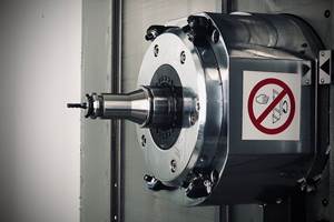
Spindle System Has Dual Contact V-Taper
Most CNC machining centers use one of two spindle systems. The most common system is the solid V-taper. Gaining in popularity is the hollow shank or HSK-type spindle system.
Most CNC machining centers use one of two spindle systems. The most common system is the solid V-taper. Gaining in popularity is the hollow shank or HSK-type spindle system.
The two systems are not interchangeable. A V-taper type tool will not fit a HSK spindle and vice versa.
The most significant functional difference between these two spindle systems is that HSK provides dual contact between the spindle face and taper while a conventional V-taper only makes taper contact. A new spindle system from Daishowa Seiki Company, Ltd. (Awaji, Japan) is designed to provide the dual contact advantages of an HSK system for solid body, V-taper tooling.
Although the new system, called Big Plus, requires a special toolholder and spindle, it is fundamentally V-taper style. As such it is interchangeable with conventional V-taper tooling. A No. 50 taper Big Plus spindle will accept either a dual contact tool holder or a standard No. 50 V-flange tool holder. Shops with machining centers equipped with these new spindle systems can continue to use their existing store of conventional V-taper tooling—which usually represents a significant investment.
A standard V-taper tool system is designed to make contact along a fixed taper in the machining center spindle. The tool is held firm against this taper by a drawbar mechanism. When a conventional holder is seated in the spindle, there is a 3 mm gap between the tool holder flange and the spindle face.
As machining spindle speeds increase, shops are finding that V-taper tooling systems may lose some dimensional accuracy due to centrifugal forces imposed by high rotational spindle speeds. The mouth of the machining center spindle can grow slightly (it's called bell mouthing) at high rpm and as it grows the V-taper tool, which is under constant drawbar pull, moves up the expanded taper.
On high tolerance applications, this slight pull back of the cutter can affect dimensional accuracy of the Z-axis. Pull back can also cause the toolholder to stick in the spindle.
Dual contact, involving the toolholder shank (taper) and the toolholder flange, is a method to eliminate pull-back of the toolholder. Precision machining for the spindle bore, toolholder taper and flange creates a connection that allows the taper and face to seat at the same time thus creating dual or simultaneous contact on the two surfaces.
The V-taper contacts the spindle taper and flange contact on the spindle face make a solid union in both the axial and radial planes. In operation, dual contact tool holders are resistant to axial movement because the face contact prevents the toolholder from being pulled up into the spindle at high speed.
An additional machining benefit is improved cutter rigidity from the extra contact area created by spindle face contact added to the taper contact. With dual contact systems, the cutting tool generally takes higher radial forces because the flange contact plus the taper contact combine to resist deflection.
To achieve dual contact for the tool shank taper and the flange, 1.5 mm is added to the spindle face and 1.5 mm is added to the toolholder flange. The taper is not changed.
Adding this material effectively closes the 3 mm gap between the spindle face and the toolholder flange. Eliminating the gap allows these tools to have dual contact.
The ability to interchange these toolholders comes from standardizing the V-taper fit between the tool shank and the spindle taper. Therefore, standard tools may also be used on this system.
The only measurable difference when standard V-taper tools are used is that the gap between a standard V-taper tool flange and the new spindle is 1.5mm instead of 3mm. Gage line for the tools is not affected.
Conversely, like sized Big-Plus tools will operate in standard machining center spindles. In these applications, the gage line is unaffected but the flange-to-spindle face dimension is 1.5mm.
As shops move production rates continuously up the high speed curve, a rigid connection between toolholder and spindle becomes critical. Which spindle system will prevail and become the standard remains to be seen.
In the meantime, shops might consider hedging their spindle system bet by specifying one that can provide the technology for rigid toolholder spindle connection, necessary in high speed machining applications, yet doesn't require total abandonment of existing tool inventories.
Related Content
IMTS Takeaways From the Modern Machine Shop Editorial Team
The first in-person IMTS in four years left the MMS editorial staff with a lot to digest. Here are a few of our takeaways from the show floor.
Read MoreMaking the Most of Mixed Toolholder Assemblies
While nearly all ER systems will have cross compatibility, they’ll have small differences across manufacturers that make their implementation at the shop level not as standard.
Read MoreHow to Troubleshoot Issues With Tool Life
Diagnosing when a tool is failing is important because it sets an expectation and a benchmark for improvements. Finding out why gives us a clue for how to fix it.
Read MoreT.J. Davies Retention Knobs Maximize Cutting Tool Life
Custom-made retention knobs are sized to fit the machine tool and spindle or toolholder to extend the life of existing machine tool assets.
Read MoreRead Next
The Cut Scene: The Finer Details of Large-Format Machining
Small details and features can have an outsized impact on large parts, such as Barbco’s collapsible utility drill head.
Read More3 Mistakes That Cause CNC Programs to Fail
Despite enhancements to manufacturing technology, there are still issues today that can cause programs to fail. These failures can cause lost time, scrapped parts, damaged machines and even injured operators.
Read More






.png;maxWidth=300;quality=90)

