
STEP NC—The End Of G-Codes?
In the not-too-distant future, the only machine tool input you'll need is a Web page.


Dr. Martin Hardwick heads up STEP Tools, Inc., the Troy, New York-based software development company leading the Super Model project.
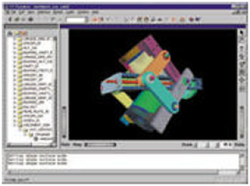
STEP allows a single database of 3D product information to be accessed by several users regardless of the different computer platforms involved. Where several companies may be producing different parts for a complex assembly with critical tolerances, having a single shared database greatly simplifies product data management and ensures that mating parts and sub-assemblies can be manufactured effectively.
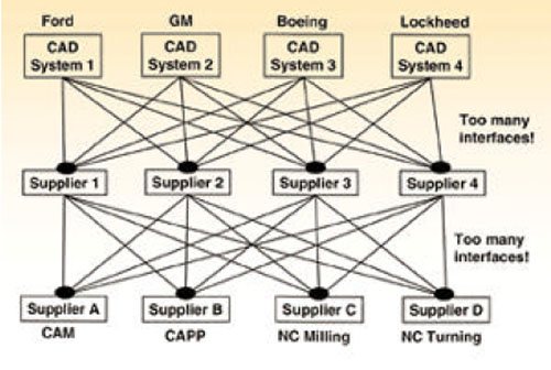
3D Model data is not used in manufacturing because even as simple supply chain must rely on too many interface among unlike computer systems. Suppliers 1 to 4 are subcontractors and job shops. Suppliers A to D are software solution suppliers serving various applications.
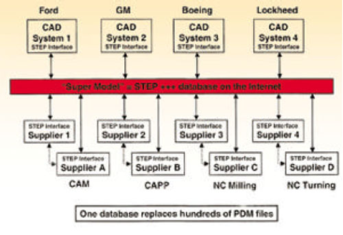
The super model solution seeks to replace hundreds of product data management files with one database from which data may be shared via the Internet. The translators, editors, converters and postprocessors require to exchange or reformate product files are unnecessary.

A Bridgeport V3XT milling machine like this one is being outfitted with a CNC customized with special software. This software will enable it to interpret the super model database and use the information to machine the part without a conventional G-code program.
Imagine this: You call up a Web browser on the PC-based CNC at your machine tool. You go to a certain Web site. From a menu on the home page, you select one of the databases it accesses. A 3D image of a workpiece comes up. You click on an icon in the task bar and check a few parameters and default settings on a pop-up window. Then it's a click on the CYCLE START button. The spindle motor starts to whir, axes begin to move, coolant spurts out and chips are soon bouncing off the Lexan panels in the machine guarding.
According to efforts underway right now, it won't be long—a couple of years at most—before this scenario depicts how most shops will be running their machine tools. NC part programs as we've known them for almost 50 years will become passe. All that the machine tool controller will need is the digital product model represented by the 3D image on the Web page.


The CNC won't use G-codes. Everything it has to know about how to move the cutting tool is in the product model's database. There will be no need for creating a new and separate file of tool path data. Tool paths will be figured out in the CNC itself, based on the product model. That means there's no need for post processors either. Data will be formatted for execution by the machine within the CNC. And because the product model won't change, it will be available for machining "hard copies" whenever and wherever needed.
"Whenever" means as long as the product's life cycle is on-going. Twenty-five years is a typical life span for aerospace parts, for example. Neither changes in computer technology nor advances in machine tool technology over the years would affect the usability of the product model as machine tool input.
"Wherever" means anywhere an adequately equipped shop has authorized access to the product model database. With the Internet, that access is worldwide. Parts could be machined anywhere in the world through a global supply chain, with the digital product model serving as the universal "NC part program."
What will it take to make this dream come true? How much more has to be done to get there? How close are we right now?
The First STEP
The biggest step in this direction has already been taken. It's STEP, the Standard for the Exchange of Product model data, a comprehensive ISO standard (ISO 10303) that describes how to represent and exchange digital product information. STEP replaces IGES as the means by which graphical information is shared among unlike computer systems around the world. The big difference is that STEP is designed so that virtually all essential information about a product, not just CAD files, can be passed back and forth among users.
The core of the standard is a library of engineering definitions that can be assembled into various "application protocols" customized for the product models needed by particular industries and activities. A common library covers geometry, topology, tolerances, relationships, attributes, assemblies, configuration and other characteristics. New product models can be added as the need arises.
An extension to STEP has been created to cover product information related to CNC machining. This is STEP NC. STEP NC forms the basis for the scenario that caught your attention at the beginning of this article. The development effort to make STEP NC product model data usable as direct machine tool input has already progressed substantially.
In May 2000, a prototype for the sets of data required to add machining information to the product model of a test part was demonstrated. A later phase of this project will develop the machine tool controller capable of accepting this "super model" as input. The current test part is a milled workpiece. Turning and grinding are on the horizon. The "super model" demonstrated in May used an emerging Internet language called XML to add information about machining strategy, tool path planning, and tool selection. XML makes the resulting database "Internet ready'—a key requirement for global e-manufacturing.
STEP Vs. IGES
To understand STEP NC and where it's headed, a look at STEP and its relationship to IGES is the place to begin. IGES was about exchanging data and only the data contained in graphics files. STEP is about sharing data, allowing parties to work together by communicating information interactively.IGES had its start 20 years ago when designers and engineers were turning to computers to create product designs. Instead of drawing lines and segment of circles on paper to make graphic representations of what a product should look like, they started making those lines and arcs on a computer screen. The completed design could be saved as a digital file. Although creating the original design file might take longer than preparing the engineering drawing on paper, the design file could be quickly copied, modified, printed and otherwise manipulated. These time savings more than made up for the extra time it took to prepare. Moreover, the digital nature of the design file allowed it to contain much more information in a much more flexible format.
One big problem quickly emerged. The computer-aided design (CAD) systems used to create these digital design files were not compatible with each other. A design created on a Computervision system was meaningless to an Applicon system, for example. Companies with unlike CAD systems could not exchange CAD data.
The effort to resolve this situation got underway in the spring of 1980. Representatives of U.S. user groups, vendors and standards organizations began meeting regularly to create a neutral, non-proprietary database structure and data format for CAD files, dubbed the Initial Graphics Exchange Specification (IGES). In theory, CAD files translated into IGES could be exchanged with any CAD system that could translate IGES files into its own proprietary format.
Although IGES eventually became a workable, if imperfect, approach to exchanging CAD files, a major shortcoming with this approach became apparent right away. IGES allowed one system to communicate the lines and symbols of a computerized engineering drawing, but IGES failed to communicate the meaning of the information the drawing was intended to convey. It did not provide a reliable means by which product features could be transmitted with the geometry so that computer-based applications could "understand" the engineering drawing.
While IGES was being developed and gradually made more functional as it moved through the standards formation process, efforts to develop a true "product data exchange specification" were launched. The goal of this effort was to capture and convey "logical" information about product features and provide "physical" mechanisms for data exchange. Originally conceived as a U.S. initiative, this effort was soon seen as requiring international participation.
By 1984, this international effort to develop a Product Data Exchange Specification had been established under the auspices of ISO, the international standards making body. The goal was to define the methods for creating product data models that could be interpreted by computers. These models were intended to allow the exchange and sharing of product data in a way that the meaning of the data would not change throughout the product life cycle.
The international standards covering these product data models became known as STEP. For the last 15 years, various groups and committees (mostly comprising users rather than vendors) have been meeting regularly to develop standards for product data models. They have made considerable progress. Because the STEP standards are now sufficiently developed to cover all of the original purposes of IGES, IGES will receive no further development and refinement. STEP has officially taken its place.
By July 2000, every major and almost all minor CAD system vendors had STEP translators in the latest releases of their CAD products. Moreover, these translators have been tested for conformance and interoperability. With only a few exceptions did any of the translators fail to operate effectively. (Indeed, one of the innovative features of the STEP formation process was the early commitment to include testing procedures for assuring that STEP-compliant systems would truly function as intended. This provision may have slowed development but it appears to have paid off in the end.) In short, STEP is working. According to industry analysts, more than one million STEP enabled CAD stations are in place around the world.
The Super Model Database
The challenge for the Super Model project is to create interfaces that bring together the information defined by STEP and STEP NC. Product geometry can be defined by one STEP application protocol. Product features can be defined by another STEP protocol. Machining operations can be defined by STEP NC. However, all three types of data and others must be integrated in a complete product model database. Moreover, this database must be Internet compatible.Starting with product geometry in the STEP format is the easy part because STEP translators are built into most CAD systems these days (and they handle 3D geometry, doing so more effectively than IGES ever did, apparently). The super model test part happened to be created in a ProEngineering workstation.
STEP NC establishes a hierarchy of workingstep supertypes/subtypes. In other words, it breaks down every machining operation into the steps required to perform the operation. These steps include actions to be taken as well as data (such coordinates of point-to-point motion) to be applied. These steps are then linked to the appropriate part model geometry to fill in the values. STEP Tools is setting up tables to match workingsteps, workingstep-methods, workingstep actions, and machined features.
A key part of STEP Tools approach to the super model database is the use of XML in its interfaces. XML, the eXtensible Markup Language, is a vendor-neutral data exchange language for passing information, not just data, across the Internet. XML allows data to be "tagged" so that software applications reading the database can identify what type of information is stored in the database and extract the data that is needed. HTML, the Hyper Text Markup Language, is a similar"metadata" language that the Web uses so that text can be displayed no matter what Internet browser happens to read it. XML offers a comparable level of interoperability. An XML standard for STEP is nearing completion. This standard will ensure that all data in a product model is "tagged" in the same way.
Ultimately, XML ensures that a CNC networked to the Internet will be able to find the information it needs from the product model database to machine a part.
Down To The CNC
The goal for the Super Model project is to show how these features can be cut on a machining center using the product model as the NC part program, so to speak. One of the subcontractors deeply involved is this phase of the program is Electro-Mechanical Integrators, Inc. (EMI) of Franconia, Pennsylvania. Engineers at EMI are writing new software for a Bridgeport control unit that will enable it to accept STEP NC data. (The company has considerable experience with Bridgeport control units and is the factory-authorized support and repair agency for the Bridgeport DX32 control.)According to Bart Stater, head programmer of EMI, this effort requires a customized command parser and command interpolator to process STEP NC. "Essentially we are creating a new CNC protocol to interpret the information in the product model in real time. This software will extract the data it needs to determine axis moves, get the specified tool, and issue commands. It will not need or use G-codes," he says. Otherwise, the I/O structure and servo system of the machine remain the same. He notes that this concept assumes that the CNC will be networked to a file server that receives and stores data, most likely through an Internet connection.
EMI is looking at two approaches to configuration of the CNC. One approach runs all of the executive software in the CNC's internal processors. Another approach uses a "PC front end" interfaced to the CNC. The PC would process the STEP NC data and spoon feed it to the CNC, filling a buffer with blocks of data on demand. This approach would ensure that the CNC is not starved for data while the product model is processed.
In November 2000, EMI is scheduled to demonstrate actual cutting of the three selected workpiece features on the test part. Although the concept could be proven with a simulation of the machining operations, cutting chips is a more convincing demonstration. "We want to show the CNC accessing the product database on the Web, finding the features to be machined, then generating commands to drill the hole, mill the slot and machine the pocket," Mr. Stater insists.
STEP Tools is also working with the Lawrence Livermore National Laboratories, where a STEP NC interface is being developed for the OMAC (Open Modular Architecture Control) project. Additional shopfloor tests and demonstrations of STEP NC are set to take place at a production machining facility operated by General Dynamics Land Systems in Scranton, Pennsylvania. A pilot project at the Jet Propulsion Laboratory is also in the proposal phase awaiting funds.
Art To Part
Those three words sum up the promise of STEP NC and the Super Model project.From a shop floor viewpoint, art to part means the intermediate steps of creating an NC program are eliminated. Most of those intermediate steps necessitated a transformation of product data, causing data files to proliferate. Part geometry had to be translated, reconstructed or edited. The edited, translated or reconstructed geometry had to be processed to generate tool paths. Tool path files had to be post processed to suit the requirements of the machine tool and control unit combination. Postprocessed files were often edited on the shop floor. In short, one piece of part geometry begot hundreds by the time the part was actually cut from metal.
From a design and engineering viewpoint, art to part means that design and manufacturing can be managed with a single database. Just as data files need not proliferate down the supply chain, they need not proliferate across the manufacturing organization. Product data can be shared between products, between corporate divisions and between applications. The Internet will make this sharing of data global and virtually instantaneous.
These CAM functions become the domain of intelligent controllers with on-board CAM software. This software will generate the movements necessary to make the parts after the appropriate parameters have been set on the CNC. "The on-board CAM software is there to do the last minute custom tool path generation using selections made by the operator," Dr. Hardwick says. Intelligence built into the software stops the operator from making mistakes or using less than optimum settings. "It's a huge opportunity for the CAM industry. This software will be a required component of all future CNCs," Dr. Hardwick contends.
Vision
With the development of STEP NC, what's happening is not simply the re-shaping of CNC. It is the reshaping of manufacturing. And in the vision that is emerging, the CNC machine tool will be more important than ever.STEP - Internet Links
1. STEP-NCwww.steptools.com/library/stepnc
STEP-NC is a worldwide effort to extend STEP to define data for NC machines. These pages include an overview of the project, and the specification.
2. Interoperability Success Stories: STEP
http://www.mel.nist.gov/msid/sima/daratech
Boeing Commercial Aircraft, Boeing CSTAR, Delphi Automotive Systems, Lockheed Martin
3. STEP Glossary of Terms and Acronyms For The Technical at Heart
http://pdesinc.aticorp.org/Glossary.htm
This link provides definitions for commonly used terms in the context of STEP.
4. PDES, Inc.
http://pdesinc.scra.org
An International industry/government consortium accelerating the development and implementation of STEP.
Worldwide news of STEP including press releases and announcements
5. Lockheed Martin Releases News on STEP implementation
http://www.mel.nist.gov/msid/98whatsn/3-4-98.htm
As part of its ongoing effort to foster product affordability, Lockheed Martin Tactical Aircraft Systems (LMTAS), in Fort Worth, Texas, recently implemented an international data exchange standard known as the Standard for the Exchange of Product Model Data, or STEP, on its F-16, F-22, Joint Strike Fighter, F-2 and KTX-2 programs.
6. Automotive Interoperability Cost Study
http://www.mel.nist.gov/div826/msid/sima/99ovwvis
What is the economic cost due to lack of interoperability in the automotive supply chain? Conservatively, One Billion Dollars Per Year! Conducted with NIST Strategic Planning and Economic Assessment office in March 1999. This slide presentation is easy to use and study.
7. Publication: STEP the Grand Experience
http://www.mel.nist.gov/msid/99whatsn/10-1-99.htm
The Manufacturing Engineering Laboratory of the National Institute of Standards and Technology is proud to announce its book publication, "STEP the Grand Experience."
8. Fundamentals of STEP Implementation [PDF]
http://www.steptools.com
This white paper walks you through a the initial stages of a typical STEP implementation project. You will need an Adobe Acrobat viewer to read this.
9. STEP - Information Sources
http://www.nist.gov/srd/astm/astm-ym/tsld016.htm
http://www.tc184-sc4.org
SOLIS a repository of STEP working material on the Web.
10. Investigating the STEP Data Standard at No Cost
http://www.steptools.com/translate
For those who are interested in exploring the STEP Data standard, STEP Tools, Inc. offers a free Online Data Translation Service. CAD users wanting to convert 3D data to and from STEP part files will find a variety of translation options, including popular graphic data formats. To date, over 8000 data translations have been
performed online.
11. European STEP-NC Project
http://www.step-nc.org/
This site is the hub for the European Perspective of STEP.


Read Next

The Cut Scene: The Finer Details of Large-Format Machining
Small details and features can have an outsized impact on large parts, such as Barbco’s collapsible utility drill head.
Read More

3 Mistakes That Cause CNC Programs to Fail
Despite enhancements to manufacturing technology, there are still issues today that can cause programs to fail. These failures can cause lost time, scrapped parts, damaged machines and even injured operators.
Read More