
The Flow Through CAM
The route from CAD to CAM to CNC can meet blockage both upstream and downstream from the programmer. However, this shop cleared away most of the obstacles to efficient electronic transfer just by updating its CAM system. The results include a new level of efficiency and new capabilities for a 10-year-old machine.
.jpg;width=70;height=70;mode=crop;format=webp)


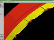
Figure 2. There are a number of reasons why even the best translator can't reproduce every model from IGES data. But the CAM system General Tool uses makes it relatively easy to work with even these incomplete files. In this case, the model on the left arrived without boundary surfaces. However, just a few clicks with the mouse can trim each surface back to what the designer intended.
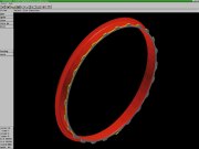
Figure 3. Five-axis machining with the turn-mill machine provided the ideal way to machine this 65-inch jet engine mounting ring. The part isn't round; it's elliptical by 0.25-inch. Also, the taper angle varies by about five degrees around the inner circumference.
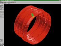
Figure 1. This solid model represents an aircraft compressor casing. Through an improved ability to import customer design files, General Tool has cut programming time for the typical part like this by about 200 hours.
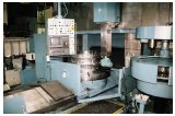
This vertical turn-mill machine can now be programmed for continuous five-axis machining. The 71-inch diameter table indexes to provide on rotary acis. Changing to a pivoting live-tool head provides the other.
Imagine the programmer as a river pilot. The part geometry is his raft, and his river flows from the customer's CAD system at its source, into his company, and downstream to the CNC machines on the shop floor.
Every machine shop with a CAM system wants this river to flow freely. The CAD file should be imported without error, and the programmer should generate usable NC code after just selecting the right tools, stock dimensions and machining routines. In other words, the pilot makes strategic course corrections, but otherwise lets the design ride the current all the way to the machine tool.


Some CAM-equipped shops have achieved this ideal. However, in far more shops, the flow is instead interrupted by paper. Designs that start in a customer's CAD system become hard copies, and programmers routinely must work from these prints to repair—even recreate—the initial geometry. That is to say: What may appear to be a perfectly good raft actually can't complete the journey, forcing the pilot either to patch the raft or build another just like it. Why is this?
Many reasons. And almost any CAM user interested in importing customer data can rattle them off. Maybe the customer refuses to release electronic files. Or maybe the designer missed some of the fine-detail work of connecting all of the features into the single, continuous model essential for CAM. Or, maybe something was lost in the CAM software's translation of the CAD output—an imperfect process, even for the best systems.
General Tool Company (Cincinnati, Ohio) has met all of these obstacles. However, the translation problem was the first and most vexing. The 250-employee contract manufacturer machines complex parts—and often produces entire assemblies—for industries including aerospace, marine and power generation. NC code for all of the shop's intricate jobs used to be generated the same way—via programmers who manually entered geometry into a CAM system that had served the company well for years. But when the company first tried to bypass this time-consuming step by importing customer CAD data supplied in the commonly used IGES (Initial Graphic Exchange Specification) format, the software fell short of this task. The files arrived too garbled and disconnected to use, even though the original CAD files appeared sound. Trusting its CAM system, and having heard of the limitations of IGES, General Tool's first reaction was to suspect that IGES simply didn't work.
Meanwhile, the company also was limited by a second blockage in its process. While the translation problem dammed the flow from CAD to CAM, the flow from CAM to the machine tools left the shop cut off from some of its most sophisticated production capabilities. Two large-envelope machines capable of continuous five-axis machining—one of them a rare variety of vertical turn-mill machine—were both programmed at best only to machine with one rotary axis, never to feed in both axes to make a contoured cut. The shop simply lacked any software to let it program this complex work. In fact, for the shop's long-standing CAM system to program in just four axes required a costly custom processor.
As a result, just as the shop couldn't work with electronic files, it also couldn't command all of the capabilities in its arsenal. And for a time, the shop accepted this limitation.
But no longer. Customer demands were changing and so were business opportunities, and both of these shifts led General Tool to take a second look at its process, and at the state of CAM software available. What the company discovered is that the latest CAM technology can indeed carry complex designs efficiently through to complex machine tools. IGES can work, and non-standard machines can be programmed economically.
The company's new process still isn't perfect. Even now, programmers must often manually input data from customer prints. However, creating the tool paths for a part like an aircraft compressor casing (see Figure 1, at right) now takes about 200 fewer programming hours than before. And if continuous five-axis milling can now be used to machine the part more efficiently, then the production time is shorter, too.
The shop achieved its more capable process, both upstream and downstream from CAM, by shifting much of its programming work to more up-to-date CAM software. No one feature of this software—Surfcam, from Surfware, Inc. (Westlake Village, California)—is alone responsible for undamming the flow. However, General Tool now takes advantage of several features it lacked in other CAM systems it has used, including (1) "flavored" IGES translation, (2) an interface for manipulating complex surfaces, and (3) five-axis programming capability, available through a postprocessor that can be configured cheaply even for an irregular machine tool.
Flavorful Designs
General Tool Company saw two reasons to open a more efficient channel from its customers' designs to the capabilities of its own shop. One reason is a flourishing aerospace market. Today, General Tool sees more demand for contoured aerostructure components than at any time in the preceding decade, and therefore more incentive to unlock the continuous five-axis machining capability that has so far lain dormant.
The second reason for the upgrade is the increasingly complex designs coming into the shop. Whether or not they call for five-axis machining, designs in general are growing more elaborate, and therefore more time-consuming to recreate by hand in CAM software. The simple reason for this is that CAD software continues to grow more and more sophisticated. General Tool's customers can now create intricate models they could not have designed so easily in the past. And quite naturally, the customers want these parts to be machined.
But recreating the complex designs from prints offers more potential pitfalls than just extra programming time, says General Tool industrial engineer Greg Kramer. A two-dimensional drawing is at best only an approximation of any elaborate three-dimensional part. The drawing leaves room for interpretation, and therefore room for a costly error. And as Mr. Kramer puts it, "I don't like to put a fifty-thousand-dollar workpiece at risk until I know we have the geometry right."
However, the only alternative to guesswork is often a delay—as is illustrated whenever a detail is missing from a print. Only the most diligent designer can remember callouts for every feature of a complex design, so such omissions are common. But when the programmer discovers one, he can only place a call back to the customer. If "phone tag" ensues, then a day or more may be lost to this seemingly tiny oversight.
Due to complications like these, programming—not machining—had become the principal source of error and delay for major jobs at General Tool. Thanks in part to a process on the shop floor that was already well streamlined, General Tool's best remaining opportunity for significant savings in cost and leadtime was to reduce the time and human attention required to generate NC code. And the obvious way to accomplish this was to import the customer's CAD file directly, wherever possible, instead of working from a paper representation.
But how could the shop effect this transfer, when IGES—so it seemed—wasn't up to the job?
Well, IGES alone was not the problem. The problem also included the CAM system's difficulty with translating the IGES data back into the original model—the one that was mapped into IGES in the first place. IGES is the most universally accepted intermediary between differing CAD and CAM systems, but the format does have its limitations. And unlike General Tool's long-standing CAM system, Surfcam employs a translator able to work through many of these limitations, to import files that the old software never could.
The translator does this by sampling the "flavor" of each IGES file. Stated another way, the translator speaks the dialects of many different CAD programs, so nuances are retained in the translation. Like any language, IGES offers no single correct translation for a statement in another tongue. In the IGES format, CAD models are mapped in terms of a variety of geometric entities, including circles, arcs and multiple types of splines and surfaces. However, different CAD systems can and do map the same features in different ways, and different CAM systems may interpret different geometries from the same set of IGES data.
A flavor-sensitive translator overcomes this uncertainty by reading the identity of the originating CAD software—information available in the IGES file's header.
Equipped with this detail, along with translation algorithms allowing for the different ways that major CAD systems map into IGES, the translator greatly improves the CAM software's likelihood of reconstructing the original model, and of precisely recapturing the intent of the CAD designer.
IGES now works so well for General Tool, the company recently bought a
Catia-to-IGES translator for files supplied by its Catia-dedicated aerospace customers. According to Mr. Kramer, when a customer supplies an electronic design file now, the shop can import it into CAM, intact and complete, better than 90 percent of the time. And even when models don't translate directly into CAM, he says, features of the newer software can help General Tool speed the job to the shop floor.
Surface Finishing
Mr. Kramer cites two reasons why a programmer would not have a clean and complete CAM model from which to begin a new job. One is that the customer refuses to part with its electronic data, and it will release only prints instead. This can be a source of frustration for General Tool, because the prints can communicate only in a crude way all of the information that is already so thoroughly contained in the CAD file. Still, the company is adept at working to meet its customers' requirements.
The second reason for added programmer hours in the process is an unfinished design in which surfaces or features are disconnected or incomplete. This can be the result of incomplete or inconsistent IGES data, which the CAM software is unable to decipher completely. When this is the case with Surfcam, the software groups those features it didn't understand to a distinct layer of the design, so the programmer can locate these and quickly reconstruct them from the customer's print. However, the design also may be incomplete because the designer didn't quite finish knitting it into a continuous model. "Our customers are as busy and harried as anyone else," Mr. Kramer says.
General Tool's CAM software simplifies the job of repairing or finishing these incomplete models. In the same way that it can import complex surfaces from CAD, the software also has the mathematical ability to interpolate similar, continuous surfaces through any series of location points input by the programmer. What is almost as important to the programmer, however, is the software's ability to manipulate these entities. Surfaces can be bound in space by other surfaces. And the programmer can create complex forms by clicking on two or more surfaces, then joining, trimming and filleting them to create a single, continuous flow (see Figure 2, below).
This same construction capability also can serve the programmer when the model has to be entirely recreated from a customer's print. No single CAM system is used exclusively for this time-consuming work of inputting geometry. General Tool currently uses three different systems and assigns these jobs among them according to the company's own evaluation of the subtle strengths of each system. However, any requirement for complex surfacing presents a compelling reason to use Surfcam, Mr. Kramer says.
The software also is used whenever there is a need for five-axis machining. With the ability to program in five axes, General Tool unlocked contour-machining capabilities it had possessed for 10 years but never put to work.
Five Access
One of General Tool's most versatile machine tools is a five-axis vertical turn-mill machine produced by Italian builder Ezio Pensotti. The machine is based on a vertical table lathe driven by a Siemens 850 control. However, the table spindle also is capable of indexing to create a rotary C axis for milling and drilling operations, while a "live" tool mill/drill head pivots through a B-axis travel of ±90 degrees from vertical.
According to General Tool, Pensotti built only three units of this machine. The one in General Tool's shop lets the company achieve single-setup machining of workpieces that are both oversize, and overly complex for other machines. The live-tool lathe can mill parts up to 78 inches in diameter by 78 inches high, and it can turn parts even larger in diameter than this.
However, for the first 10 years, General Tool machined only with the C axis, using the B axis only to index tools outside the cut. The newer CAM software offered a way to change that. The software includes not only five-axis programming capability, but also a generic postprocessor offering a way to take advantage of this feature cheaply, even for unusual machines.
The postprocessor presents a template format for data input, allowing the user to enter the control type, travels and other physical attributes of the machine. This information lets the software generate a "rough draft" of the postprocessor on its own. From there, a text editor lets the user fine-tune the code after running test cuts to measure how well this first version performs.
General Tool has used this feature to write posts for most of the 18 types of controls in its shop. But for the five-axis Pensotti machine, the job was more complex—enough that General Tool decided simply to let the vendor, Surfware, take care of it. Even so, this service cost only one-tenth of the price for the custom postprocessor permitting just four-axis machining with the shop's older CAM system.
Now, with full five-axis machining capability in place, General Tool runs parts like the one in Figure 3 (at left). This jet engine mounting ring, which looks round, is actually elliptical. Its outer diameter of approximately 65 inches varies by 0.25 inch. Also, the angle of its tapered inner diameter varies by about five degrees around the circumference. This requires an endmill to pivot in the B axis, while the machine follows the ellipse by interpolating in X, Y and C.
General Tool's Greg Kramer says that more parts demanding such complex angular tool paths will be the future of the company. Last year, General Tool installed its second five-axis machine—from Giddings and Lewis—and it is currently installing additional five-axis machines from Cincinnati Machine and DMG North America. As all of these attract more and more complex work from customers, Mr. Kramer says, direct electronic transfer of design files will become more and more important.
The move away from paper has already begun. In fact, even customers who insist on providing hard-copy designs have begun to specify complex mathematical surfaces. In many cases, the part drawing now includes a surface call-out that refers to a file on a diskette. So the surface, at least, is provided electronically.
To Mr. Kramer, where this is headed is clear. "A growing percentage of the designs we see just can't be communicated on paper."
To contact General Tool, phone (513) 733-5500.


Related Content

CNC Machine Shop Honored for Automation, Machine Monitoring
From cobots to machine monitoring, this Top Shop honoree shows that machining technology is about more than the machine tool.
Read More
Fearless Five-Axis Programming Fosters Shop Growth
Reinvestment in automation has spurred KCS Advanced Machining Service’s growth from prototyping to low-and mid-volume parts. The key to its success? A young staff of talented programmers.
Read More
Five-Axis Changes Weldments Into Monolithic One-Piece Parts
Moving from welding to five-axis machining enabled Barbco to redesign its weldments as monolithic one-piece parts with improved strength and repeatability.
Read More
Which Approach to Automation Fits Your CNC Machine Tool?
Choosing the right automation to pair with a CNC machine tool cell means weighing various factors, as this fabrication business has learned well.
Read MoreRead Next


3 Mistakes That Cause CNC Programs to Fail
Despite enhancements to manufacturing technology, there are still issues today that can cause programs to fail. These failures can cause lost time, scrapped parts, damaged machines and even injured operators.
Read More
The Cut Scene: The Finer Details of Large-Format Machining
Small details and features can have an outsized impact on large parts, such as Barbco’s collapsible utility drill head.
Read More