
Using The Machine Tool As A Gage
On-machine inspection probing keeps jet engine production flying.


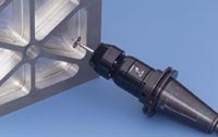
Fig. 3—Custom probe designs allow special features such as the undercut walls of the iso-grid to be measured effectively.
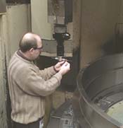
Pratt & Whitney often machines large jet engine components in fixtures that constrain the part in a way that simulates the mounting arrangement in the engine. Inspecting and verifying these parts on the machine proves to be highly advantageous. Jim Beck, a manufacturing systems engineer, replaces a stylus on the T-probe assembly used to inspect this component.
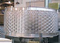
Fig. 1—This fan containment case is almost 10 feet in diameter and nearly 5 feet high. The exterior is characterized by an iso-grid, a series of triangular pockets formed by walls with an I-beam cross section that reduces weight while optimizing strength.
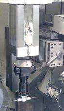
Fig. 2—This T probe is used on VTLs. Such probe assemblies perform several probing functions, but each assembly takes up only one station in the toolchanger.
Pratt & Whitney jet engine plants began inspecting and verifying parts on the machine tool more than 10 years ago. A combination of factors was driving the company in this direction, but the main motivation was the need to make 100 percent good parts in the lowest possible cycle time. A variety of calibration, probing and process control techniques made this move possible. Since then we have continued to develop and refine our strategies and techniques as new developments from suppliers such as Renishaw Inc. emerge to extend and strengthen this concept.
Our experience is testimony to the effectiveness of integrated machine inspection for high value parts produced in flexible manufacturing schedules.


On-machine inspection by automated probing routines has produced these benefits at Pratt & Whitney. It has:
- Avoided investment in additional special coordinate measuring machines
- Reduced gage cost
- Reduced lead-times
- Enhanced statistical process control with instant feedback about process capability
- Automated Processes
- Reduced error
- Improved machine tool accuracy
- Enabled design for manufacturability
This article presents our experience in:
- making sure machine tools and processes are capable of producing parts to specification;
- inspecting and “buying off” parts on the machine tool, while still fixtured, by achieving process control to traceable standards.
An Early Adopter
Pratt & Whitney became an early adopter of on-machine part inspection and acceptance of jet engine components. The methods described originated at Pratt & Whitney’s Middletown, Connecticut, large commercial jet engine manufacturing operations. On-machine inspection (OMI) was implemented out of practical necessity in one of our Middletown business units to deal with time, cost and accuracy liabilities from traditional post-process inspection by coordinate measuring machine (CMM) or hard gaging. OMI was first applied to large commercial jet engine components—cases, disks and hubs—that are produced principally on vertical turning centers and horizontal boring mills. After successful implementation at the Middletown unit, on-machine inspection has been strategically adopted by other Pratt & Whitney manufacturing units.
Besides the universal desire to reduce throughput times and in-process costs, we turned to on-machine process verification, feedback and correction to address specific cost and logistical issues:
Post-process part rejection. A part that fails post process inspection by CMM or gaging typically results in rework, repair or scrap costs. On a complex component with high accumulated value, that failure can represent a financial loss of up to $50,000. Furthermore, components are produced as part of an engine build set. Rejection of a key component can delay engine build and delivery, possibly invoking contractual financial penalties. On the other hand, in-process inspection offers the opportunity for process feedback and correction to avoid part rejection.
Parts not physically suitable for CMM inspection. Part size—such as a fan containment case (Figure 1) that is 118 inches in diameter and 58 inches high—can make a CMM with sufficient measuring range prohibitively expensive. Furthermore, to ensure geometric accuracy, we try to hold components in fixtures during machining in a similar manner to how they will be constrained when assembled in a jet engine. When removed from the machine tool and the fixturing for loading on a CMM, parts can change dimensionally enough for a good part to be rejected. Aluminum parts are particularly susceptible.
Gaging slow, complicated and costly. The sheer size and number of dedicated custom gages needed for our part variety would present a tremendous financial investment, as well as a logistical nightmare to build, store, calibrate and maintain. Physical gaging is a slow, laborious, staff-intensive process, and it runs counter to plant efforts to shorten and automate processes. By comparison, probing programs run on the machine’s CNC. This enables machines to run for extended auto-time and allows operators to attend to other duties. Probing programs automatically apply compensation, avoiding the need with manual gaging to enter offsets into the control. Incorrect data entry can be a source of error leading to mis-machined parts.
In the early 1990s, Pratt & Whitney assembled a cross-functional team (see box) to develop and implement strategies for enhancing process control and integrating automated part inspection, starting with the machining process for iso-grid fan containment cases—large, complex, high value structures with relatively thin walls. The strategies, methods and techniques that follow have been practiced since 1994-95 in Pratt & Whitney jet engine manufacturing.
| Cross-functional Team Members | |
|
Jeff McCoy |
Production Technical Leader M.E./Programming |
Achieving Machine Capability
The first challenge in process control is ensuring that the machine tools are capable of delivering and holding part tolerances. We treat a machine tool just like we treat a gage. It has to be calibrated on a periodic schedule, or in between if a problem develops. We do laser calibration of machine tools.
After calibration (and any machine adjustment, if indicated), we measure machine accuracy by probing position against a precision step bar. This procedure gives traceability back to the National Institute of Standards and Testing and sets a new baseline for the machine.
We have our own internal calibration standards written for machine tool types, which guide the technician on what to do and how to do it. The procedure not only considers calibration of individual axes, but also geometric effects. For example, the calibration results for pitch, roll and yaw can be entered into a spreadsheet program, which will calculate the cumulative error and report whether the machine meets or fails the established standards.
Our standards for probing programs require calibration to within 10 percent of part tolerance, no small challenge in the context of large jet engine parts with exceptionally tight tolerances. As an example, the iso-grid fan containment case cannot exceed ±0.010 inch in diameter over nearly 10 feet, 0.030 inch out of roundness in outside circumference, or ±0.004 inch on height of nearly 5 feet. Consequently, calibration of an axis to ten-thousandths of an inch is not uncommon.
We initially calibrated the full axis range of a machine tool, but we found this kept machines off-line longer than desired. Instead, we now calibrate for the work envelope, as long as there is no evidence of process deterioration. We have found this zone calibration to be effective in maintaining machine capability and significantly more efficient.
Measuring Against Artifacts
Accuracy can be introduced to a machine tool in the form of an artifact—a generic part or replica component—that has had its actual dimensions determined on a CMM at 68°F. Having the machine probe the artifact will detect any differences between the known actual dimension and the measured dimension. The differences are used to derive offsets that compensate for the current machine conditions.
In effect, an artifact serves the same function for the probe as a set master used to zero out the dial indicators on gages. An artifact can be used as well to set the part reference, telling the machine where the part is.
At Pratt & Whitney, the artifact may be part of the fixture, or it may be mounted on the machine. In some cases the artifact may simply be a gage pad. For critical features, we make the artifact process-specific. We may place a bore in the fixture to make sure that heights and angular positions are right. For the complex fan containment case, which features an iso-grid exterior truss configuration created by machining out 1,600 triangular pockets, the artifact is an actual machined pocket. Vertical turret lathes (VTLs) can have circular “race tracks” as artifacts to represent OD and ID measurement. A race track is a machined groove on the outside diameter of the turning fixture, which has been inspected and verified by our quality organization with the actual size stamped on the fixture for reference in determining offsets.
Artifacts are calibrated on a frequency determined by our quality organization.
Comprehensive Probing Strategy
The key to maintaining tight processes and quality control over engine components is the comprehensive application of probing for part and process verification and feedback.
Probing inspection programs follow this sequence:
- Datum (zero out) the tool probe
- Datum the part probe
- Establish tool offsets
- Establish fixture offsets
- Inspect features after semi-finish machining to set process offsets
- Inspect features after final machining and write data to disk
- Upload data to a common database
- Accept/reject part
Because we often use multiple probes in our inspection routines, we’ve developed self-datuming routines so that all the probes are tied together. This practice uses a probe that’s been datumed as reference for datuming another. It assures that probes are synchronized and measuring the same. Self-datuming routines are imperative to ensuring that we achieve the required accuracies.
Probing routines for new parts are tested before being accepted. To get quality approval on probing programs, we probe the new part and record all the dimensions. We then test these against an alternate method, which could be a CMM, gaging or another calibrated machine tool. The on-machine probing measurements are compared to those by the alternate method. Any difference must be within 10 percent of part tolerance for quality approval of the probing program.
To enhance probing accuracy further, trigger compensation is added to the calibration offsets. The comps recognize that probing is a dynamic activity whereby a probe may not capture the exact position of the probe hit—that is, the machine axis may travel before the probe deflection causes the machine axis position to be captured in the control. This need for compensation is determined by taking a number of hits during the development of the probing program and comparing the probe readings with the known dimensions. If we find the probe trips and moves a thousandth, we apply a trigger comp. Such adjustments are extremely fine, never exceeding more than 0.001 or 0.0015 inch.
Before cutting, we probe all the tools to be used to determine offsets from the centerline of the spindle and from the face of the spindle. You want to know where all the tool tips are. On milling and drilling applications, we may probe the number of flutes in the end mill, check for missing flutes, check for run-out, and measure diameter. We put statements in the probing programs that set tolerance windows for the tooling, so a bad tool will be rejected and the process stopped to prevent the bad tool from being used. We can also compensate for tools that are ground to a slightly different diameter.
After we do our roughing cuts, we make semi-finish cuts. We try to take the same amount of material in semi-finish as we do on the finish cut. We probe the semi-finish cut to offset for any part deflections, tool deflections, tool wear, and other factors.
We then go ahead and finish machine the part. The probes are datumed off the artifacts before performing final inspection probing. The inspection data is used to accept or reject the part and is uploaded to our AMIS (Automated Machine Inspection System) database for statistical analysis of the process.
Probe Configuration
We use some special probe configurations, particularly where multiple probe heads and styli are integrated onto one probe/toolholder assembly. Most are assembled by our toolroom using standard Renishaw probe heads, styli and components. In some cases, we have probes custom engineered and built by Renishaw. Probe assemblies save space in the tool chain, compared to storing individual probes, while assuring that the various probes have a known, fixed dimensional relationship to each other.
Probe configuration depends on the part geometry, features and sizes, how far we need to reach and where on the part we need to make the probe contact.
Figure 2 shows a T probe used on four-axis VTLs with X-Y main head and U-W axes side head. Near top right is an MP3 probe in the process of probing the side head tooling. The T at the bottom features two LP2 probes. These are used to probe part features and set part references—diameters and heights. The short styli on the upper portion of the toolholder can be used for self-datuming.
Probe configuration can be varied to part criteria. Instead of the T at the bottom, for example, we may use a “Mexican hat” probe (gull wing stylus) or a straight probe.
In addition to the T probe assembly, the VTL is fitted with a swing-out MP3 probe, mounted on the machine, that probes the main head tools. We put an artifact in the main head, then datum the swing-out probe off that. Next we datum the MP3 main tool probe (which is used to probe side head tools) off the swing-out tool probe, tying the two together. We adjust spring tension so the swing out probe is a little stiffer, enabling the main tool probe to trip first.
Figure 3 shows an MP10 probe used to measure iso-grid pockets. The disk allows measurements of I-beam undercuts and keeps the shank of the probe from contacting the grid walls.
Automating Inspection Programming
Recently we have begun using commercial software to simplify and speed the development of inspection programming by automating certain operations. We use the template features of our Unigraphics CAD/CAM system to set position and create some sub-routines. For example, we can create a sub-routine for one pocket, and then just reposition the probe to do different pockets. We’re not fully developed with graphic probing to where everything is automatic, but we’re moving in that direction.
We see inspection following the lead of machining. At Pratt &Whitney we now have 3D modeling of the machining process—machine, fixture and part—right on the screen. We can do virtual machining of the part, detect and eliminate interferences, refine cutter paths, and graphically verify the program. We can’t yet graphically simulate the inspection, but that’s where we’re headed.
We are using Vericut software for crash protection in development of inspection programs. The software verifies the positioning of the probe relative to the part.
Process Control Benefits
Part inspection data is a valuable resource for process improvement and planning.
We use generated data for process certification. Performance tracking allows a manufacturing engineer to see from the data whether the process is drifting. It gives a heads up that we’re starting to lose control of the process and we need to investigate and correct the situation before producing a non-conforming part.
Process data is used to calculate Cpk and refine strategies. Once we have demonstrated process stability and shown we can hold above 2.0 Cpk, we feel comfortable reducing our inspection sampling on parts. For example, the final inspection routine for the fan containment case in Figure 1 initially took 4 hours, much of that time in measuring the triangular pockets that make up the iso-grid truss structure. Once we had achieved sufficient history, we were allowed to change the inspection plan and reduce the number of pockets we inspect. Final inspection is now performed in less than 2 hours.
Stable process control is a particularly important part of our strategy to reduce component weight, which is key to our engine products. By being able to control thickness carefully, we can target and take weight out. The fan containment case, for example, starts out as an aluminum forging weighing in excess of 4,000 pounds. Initial processing is done on a VTL, which turns ID and OD to a wall thickness of about 3 inches. Pinch turning, with opposing heads simultaneously cutting ID and OD, helps to offset cutting forces. The case then goes to a 142-inch horizontal boring mill, which machines the iso-grid structure on the exterior. The 1,600 triangular pockets are machined out to a depth of about 11/4 inch, while grid walls are undercut to create an I-beam sectional profile. The iso-grid design provides structural strength, while the pocketing enables further weight reduction. On completion, the fan case is reduced to just 450 pounds.
There is another advantage to having inspection data collected off the machine tool. This data helps the company design parts for manufacturability using a process we call closed loop machining. We are feeding this accumulated production history back to the engineering department to help make designs more manufacturable. Design becomes more of a collaborative effort. Designers can create shapes and set tolerances to machine capabilities, resulting in higher quality and lower cost components.
For example, process capability data on the iso-grid fan case was used by design engineering to set feature tolerances within our demonstrated capabilities for a 100-inch diameter fan case for a different engine. Now process data history for both parts is being applied to the design of a fan case for still another new engine.
Powerful Enabler
In total, automation of on-machine inspection has been a powerful enabler at Pratt & Whitney. It has helped avoid capital investment, reduce work-in-process time and costs, improve machine tool accuracy, and provide feedback for process improvement and design-for-manufacturability.
About the author: Jeff McCoy is a production technical leader at Pratt & Whitney in Middletown, Connecticut. He has been with the company for 15 years.


Related Content

The Cut Scene: The Finer Details of Large-Format Machining
Small details and features can have an outsized impact on large parts, such as Barbco’s collapsible utility drill head.
Read More
Heavy Engineering: The Complex Logistics of Moving Large Machine Tools
One of our fascinations with large-format machine tools has little to do with their capabilities, but everything to do with the logistics involved with getting them up and running. Here’s how one of the world’s oldest builders of giant machine tools tackles the challenge.
Read More
ESOP Solidifies Culture of Continuous Improvement
Astro Machine Works’ ESOP rewards all employees when the shop does well, inspiring many toward continuous improvement as Astro expands its capabilities.
Read MoreRead Next

3 Mistakes That Cause CNC Programs to Fail
Despite enhancements to manufacturing technology, there are still issues today that can cause programs to fail. These failures can cause lost time, scrapped parts, damaged machines and even injured operators.
Read More

The Cut Scene: The Finer Details of Large-Format Machining
Small details and features can have an outsized impact on large parts, such as Barbco’s collapsible utility drill head.
Read More