
Variations on the Rotary Transfer Theme
A Hydromat open house event demonstrates the degree to which rotary transfer machines can be tailored to specific high-volume applications.
.jpg;width=70;height=70;mode=crop;format=webp)


Bar-fed rotary transfer machines combine multiple cutting stations around the periphery of a round, indexing table. (These tables are commonly oriented horizontally, but “trunnion-style” versions in which the table is oriented vertically are also available.) Fixured or collet-held workpiece blanks arranged around the table are indexed from one machining station to the next until all operations are completed. (Some stations are used to invert the workpiece to enable back-side machining at subsequent stations.) A finished part(s) is ejected with every index of the table.
A visit to a Hydromat open house event I attended late last year at its U.S. headquarters in St. Louis, Missouri, was timely because I was able to see a few rotary transfer machines in build that demonstrate the degree to which they can be tailored to specific high-volume applications. Although this article’s four photos constitute a random sampling, each represents a specific level of rotary transfer sophistication engineered to meet a user’s particular production needs (ordered from basic to complex).


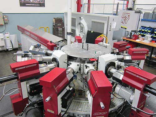
This Epic R/T 25-12 collet-style machine (above) with a single bar feeder and no vertical machining stations represents a basic rotary transfer system. It’s similar to original Hydromat designs that were hydraulically driven, but it’s CNC-controlled. As for the model number identification, “25” indicates the diameter of the barstock material it is designed to accommodate (25 mm) and “12” is the number of available machining stations.
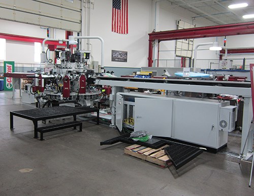
The Epic R/T 32/45-16 machine above (16 stations can be set up for 32- or 45-mm maximum barstock diameters) has two opposing bar feeders delivering stock into stations 180-degrees from each other. The operations performed are the same around each side, and two finished parts are dropped with each index. (It’s basically doing the work of two machines simultaneously.) So around each side, stock is fed into the first station, machining is performed on the next three, the part is inverted on the following one, back-side machining is performed on the next two, and the completed part is ejected on the last. Note that this setup also has four vertical machining spindles.
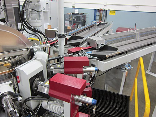
This Epic R/T 25-12 machine (above) also has two bar feeders. However, instead of opposing each other as in the previous example, they feed small-diameter barstock into adjoining stations. Plus, each has been modified to feed two bars apiece into custom workholding collets designed to hold two parts (not just one as you might expect). As a result, four parts are dropped complete with each 3.4-second table index, helping the customer to meet its very-high-production volume goal.
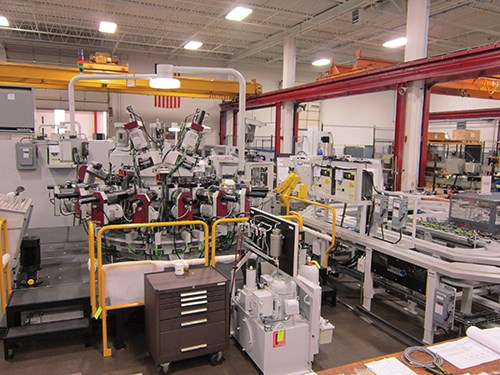
This Epic HS 16 indexing chuck shows the extent to which ancillary equipment can be added to offer a complete parts manufacturing solution, including robotic part handling, part gaging and part cleaning.


