
What Does “eAx for HMC ZzxBm_XzxYxySt” Mean?
Although "eAx for HMC ZzxBm_XzxYxySt" is an odd-looking string of letters, it is an example of precise notation for identifying sources of error in machine tool performance. The naming conventions represented by this example bring order and clarity to one company’s efforts to evaluate and improve machining results. Identifying errors correctly is essential to understanding concepts such as volumetric performance and error budgeting.

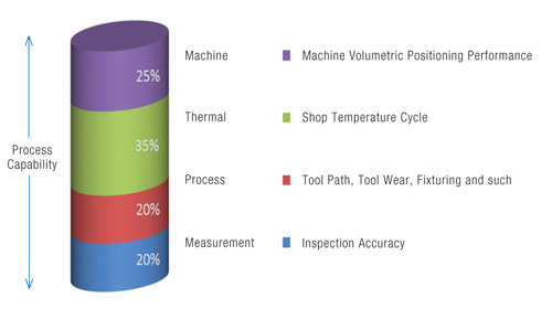
The build-up of errors in a process can be represented as a column segmented by the various sources of error. If one segment accounts for a disproportionate share of the total, the process cannot be expected to produce parts that are within tolerance.
Giving every type of machine tool configuration an exact name makes it easier to visualize and cope with inaccuracies caused by inherent errors in its structure.
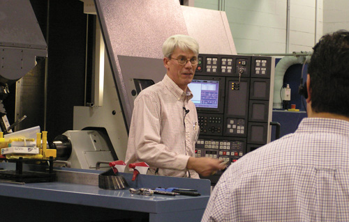
Buz Callaghan has more than 20 years of experience with coordinate measuring machine and machine tool behavior. A noted author and lecturer, Mr. Callaghan conducts a seminar on machine tool metrology several times a year.
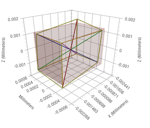
Volumetric performance is widely considered a comprehensive evaluation of a machine tool’s capability because it detects the effects of both linear and angular errors. Essentially, volumetric performance evaluates how precisely the machine can position to any point in its work cube.


Every one of us has a name. Without these names, we could hardly communicate. "eAx" is a name, too. It’s what Independent Quality Labs, Inc. (IQL) calls a Parametric Error Name (PEN). IQL, of Rockville, Rhode Island, is a company dedicated to helping manufacturers cope with the inherent inaccuracies in machine tools caused by errors such as eAx. A system to name these errors in an exact and logical way allows IQL to communicate more effectively about machine tools and their ability to produce parts that meet tolerance requirements. In this case, eAx is the name for angular error in the Y-Z plane of a machine tool axis. This particular error causes an axis to twist slightly as it moves and veer off course, so to speak.
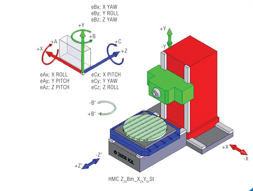
Just as this particular PEN singles out one kind of error in a certain plane of axis motion, the relationship of that axis to other machine tool axes also needs to be identified by name. Otherwise, it’s not clear where the error is occurring or what effect it will have on the overall accuracy of the machine. The title of this article gives one of those names—HMC ZzxBm_XzxYxySt. This happens to be one of the longer names, which describes a fairly complex horizontal machining center. Because machine tools are available in a virtually unlimited number of configurations, each with different relationships between the various axes, a system for creating these names has to generate an unlimited supply of suitable, logical designations to identify these relationships.


IQL has such a system, and the names are collectively called IQL Subclass Nomenclature. Names for the different types (subclasses) of machine tools are classified by the way axes are arranged. Each unique name clarifies how
the axes are "stacked" from the ground up and where the workpiece will be located within this stack. In this case, HMC ZzxBm_XzxYxySt identifies an axis in a machine tool structure like the one depicted to the right. As a matter of fact, angular error in the Y-Z plane of this axis (eAx by name) is likely to be especially troublesome because it affects the squareness of other axes in this machine configuration.
Robert "Buz" Callaghan, a senior engineer at IQL and the company founder, explains why PENs and Subclass Nomenclature are important. "Machine tools are complex electromechanical structures, and the inherent inaccuracies in these structures determine how well they can produce parts that meet the specified tolerances and will function as intended by their design. We need to be able to talk about these inaccuracies clearly so we can understand them better and deal with them more effectively. It all starts with the proper use of terminology."
Mr. Callaghan says that understanding the accuracy errors of a machine tool has significant practical value. It helps manufacturers diagnose root causes when machining processes are not providing the results they need, for example. It aids process planning for new jobs or for new manufacturing tasks. It enables shops to make more informed purchasing decisions.
Straight Talk About Accuracy
According to Mr. Callaghan, IQL’s system of precisely naming machine tool errors and the associated subclasses of machine tool types is based on definitions and naming conventions established by ISO and ANSI standards. His company’s system is a modification and extension of the systems proposed by these standards. "These standards provide a great start, but either they don’t go far enough to cover all the errors and machine tool types or they don’t easily allow new types of machines to be classified," he says.
Some other modifications IQL adopted are simply practical ones to make the names easier to read and interpret on the page, such as using upper or lower case letter and subscripts. Ensuring that minus and plus signs are used consistently and correctly to indicate direction is also a key part of this system.
Mr. Callaghan details some of the benefits of having suitable PENs and subclass names. "The simple fact that there is a multitude of PENs conveys an important insight: namely, that even common machine tool types involve many motion errors and different types of motion errors," he says. He points out that most machine tool users consider only three measures of machine tool accuracy—positioning along linear motion in X, Y and Z. That implies a simplistic understanding of machine tool accuracy and process capability. For example, this view overlooks angular errors caused by roll, pitch and yaw in linear axis motion.
Awareness of the numerous ways in which a machine tool is susceptible to inaccuracy is fundamental to such concepts as error modeling, a technique for capturing a complete picture of what is happening when machine axes are in motion. "In reality, machine tool components are making lots of subtle twists, turns and tilts as they move, and the resulting error, however slight, throws the cutter off direction," Mr. Callaghan explains. These deviations often affect part quality. The ability to diagnose the conditions that cause error and then make corrections that do the most to help a machine produce parts within tolerances is a huge benefit. "The industry has to have a method of naming errors that is adequate to clearly describe all errors present in a comprehensive model of machine performance," he concludes.
The same points can be made about the subclass nomenclature, that is, the names for types of machine tool configurations. At least two key insights come across when considering the classifications. One is that there are many ways to arrange machine tool axes and these different arrangements exhibit different performance behavior. For example, certain types of errors may be more prevalent, or have a greater effect, on one type of machine compared to another. "Whether a vertical machining center is a gantry type or a C-frame type influences which errors we need to worry about," Mr. Callaghan explains. Likewise, whether the machine provides rotary motion by tilting and swiveling the workpiece or by tilting and swiveling the spindle head is another basic distinction with ramifications for machining accuracy.
A closely related insight is that the relationships among axes are critical to understanding machine tool performance. Theorists in this field call these relationships "kinematic chains," but Mr. Callaghan prefers the term "axis stacking" because it is more helpful in conveying related concepts. In IQL’s nomenclature, each subclass name is essentially a sequential list of way planes of axis motion, given in the order in which they appear. The list starts from a fixed point on the earth, so the subclass name is literally built from the ground up. "Each subclass name creates a mental image of the machine being described. With this picture in mind, the error model for a particular machine of this type is easier to visualize," Mr. Callaghan says. This helps the machine operator or shop manager "see" where the problem lies if a machine isn’t providing the expected results.
What’s In A Name?
At this point, the names in this article’s title should start to make sense. Consider eAx. In IQL’s system, e indicates a motion error. The system specifies that this error will be given as the bandwidth of the bi-directional averages of measured deviation (usually a plus/minus value). The A in this name indicates that this is an angular error, and the x indicates that the error occurs when this axis is moving along the X axis. Other PENs for this type of machine would be spelled out in the same manner. An error model for a machine tool would typically list PENs and their numerical values in a tabular format. This type of machine requires 28 PENs to identify all possible motion errors.
As noted, the subclass nomenclature indicates that this is a horizontal machine with a worktable that moves from side to side and has a rotary table to hold the workpiece. The column provides up and down motion of the ram, which moves in and out holding the spindle and the cutting tool.
Mr. Callaghan describes a scenario that puts these names in perspective. "Let’s say a shop has to move a job running on that machine to a different type of machine with a suitable work envelope. If parts coming off the second machine aren’t meeting the tolerances that the first machine could hold, the shop needs to know why. Looking at the error models of the two machines would give us a clue as to which motion errors to check for. Another scenario would unfold if a new job were assigned to the original machine, but the machine didn’t meet tolerances for a certain feature. Again, the error model would guide us to the source of the error."
Speaking [Of] Volumes
Shops that become more familiar with the names for machine motion errors are better able to grasp more sophisticated concepts in machine tool metrology, Mr. Callaghan says. One of these concepts is volumetric performance—a comprehensive view of a machine’s precision throughout the entire work envelope that accounts for both linear and angular errors. Another concept that provides shops with greater value as "error awareness" grows is error budgeting, a way to manage error correction efforts wisely.
The concept of volumetric performance is often referred to as "volumetric accuracy," although this term has been eschewed in most metrology circles and by standards committees as a euphemistic misnomer—it sounds nice but does not reflect the exact meaning. As Mr. Callaghan points out, volumetric performance is a neutral term that doesn’t imply the accuracy or inaccuracy of the findings. Regardless of terminology, volumetric performance is getting more attention these days.
For example, many shops are looking at large machine tools to make large workpieces to close tolerances. The surge in wind turbine components and airframe components for the next generation of jetliners is one reason for this growing interest. Other shops are turning to tombstone fixturing for producing arrays of smaller parts with tight tolerances on horizontal machines with minimal operator involvement. The growing popularity of five-axis machining for 3D contours and the like is also a factor. All of these cases require a machine can reliably produce part geometry that is within tolerance, even if the part feature or part location is on the outer reaches of its work zone.
According to Mr. Callaghan, the volumetric performance of a machine tool largely depends on the extent of angular errors in axis motion. "At the factory, the machine tool builder has to take steps to minimize pitch, yaw and roll with well controlled manufacturing processes," he says. When the machine is in place, operators and shop managers have to do their part as well. For starters, they have to be sure the machine is adequately leveled and anchored when it is installed. Likewise, they have to understand volumetric performance to be knowledgeable to implement proper maintenance routines and appropriate calibration techniques. "Angular errors are key to making good parts in 3D. Without control of angular errors, you can’t get repeatable production and automation will fail," he warns.
Managing The Cost Of Accuracy
Apparently, one of IQL’s specialties is helping its clients develop manufacturing process error budgets. Error budgeting is a method to account for all sources of error so that time and effort spent on establishing adequate process capability are not wasted. As Mr. Callaghan puts it, "Error budget analysis is valuable because it combines all factors impacting feature tolerance into an easily understood framework."
Conceptually, error budgeting starts with the illustration above to the right. The column represents the overall capability that a process has to achieve. Each segment in the column represents a class of variables that cause errors, errors that can build up and "consume" what is allowable for the process to meet expectations. The sizes of the segments are proportional to the amount of error each class of variables contributes to the total build-up. The percentages shown in the illustration are typical for a capable, stable process—that is, one that is producing part features within the tolerances.
As Mr. Callaghan points out, when designing or evaluating a machining process, a planner should "budget" the contribution of each segment in this column accordingly. For example, thermal variables, which are relatively large contributors of error, may need attention. They include external factors, such as air temperature or sunlight streaming through a window onto the column of a machine, as well as internal factors, such as heat from drive motors or electrical gear. Likewise, the machine’s volumetric positioning performance has to be budgeted appropriately. Clearly, to keep this segment from getting "out of proportion," positioning performance has to stay rather
tight. That means it has to be more accurate than might be indicated if other variables are not
considered.
An error budget can also be developed for each part feature tolerance. "We can use this tool to help shops determine the most effective corrective actions if there is a performance problem," Mr. Callaghan says. For example, IQL’s methodology involves identifying the features and tolerances that are most difficult to manufacture. These are designated as "critical to manufacture," or CTM. A machine error budget is used to identify the performance parameters with the greatest impact on each CTM. These are "critical performance parameters," which Mr. Callaghan describes as required for success. They are make-or-break capabilities. In the case of an existing machine, the shop can now look at the error model that IQL has developed and make rational decisions. For example, corrective action should focus on addressing the parametric errors limiting the machine capability related to the particular part feature. A strategy for monitoring those parametric errors to maintain control of the process can also be established. In Mr. Callaghan’s experience, these "fixes" have proven to be effective and economical, often allowing a shop to forego purchasing a new machine by rehabilitating an existing one.
Likewise, shops looking to add capacity were able to use error budgeting to refine the specifications for a new machine. Specifications that pinpoint the PENs associated with CTM features help guarantee a successful application. Disputes about machine performance are less likely to occur, and they are easier to resolve when required process capability is spelled out in no uncertain terms.
Let’s Be Clear About This
"Error budgeting demonstrates the value of the clear thinking and clear communication about machine performance," Mr. Callaghan concludes. "PENs and subclass nomenclature provide a precise vocabulary with which to think and talk more clearly."


Read Next

Keeping Accuracy Within Reach
Part quality is at risk if a machining center cannot hold tolerances at the farthest reaches of its work envelope. This makes volumetric accuracy a key indicator of a machine's performance. One machine tool builder discusses the implications.
Read More
The Cut Scene: The Finer Details of Large-Format Machining
Small details and features can have an outsized impact on large parts, such as Barbco’s collapsible utility drill head.
Read More
3 Mistakes That Cause CNC Programs to Fail
Despite enhancements to manufacturing technology, there are still issues today that can cause programs to fail. These failures can cause lost time, scrapped parts, damaged machines and even injured operators.
Read More