
What To Consider When Adding Angle Heads
Angle heads can enable a three-axis machine tool to be more versatile. That said, this shop explains that there’s more to getting started using them than simply loading them into a machine’s spindle.
.jpg;width=70;height=70;mode=crop;format=webp)
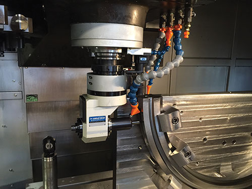
Cogitic Corp. uses right-angle heads like the one shown here to enable its Toyoda VMC to perform horizontal milling, drilling, thread milling and related operations. This minimizes setups and helps to maintain tight feature-to-feature accuracy for the challenging parts it machines.
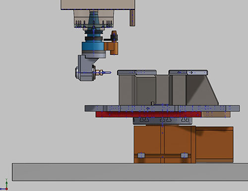
The CAD model shows that the face of the right-angle head is coplanar with the spindle centerline. Knowing this, Cogitic uses parametric programming when the angle head is called up to establish a temporary global shift to be made in the X axis for each different tool length so the location of the tooltip is known.
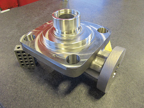
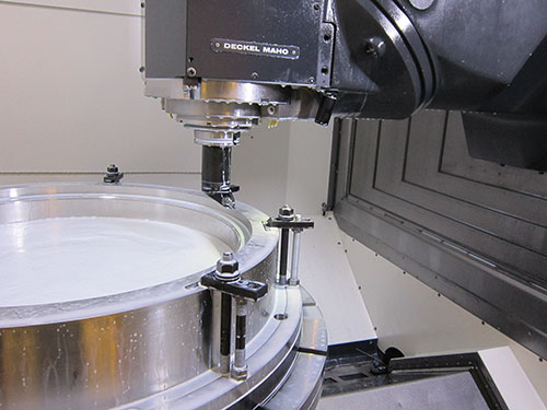
This part is an ideal candidate for machining with a right-angle head. It was previously machined in two setups, one with it fixtured flat on a VMC’s table and the other with it bolted to an angle plate. Now, the right-angle head is used to complete all of those operations in one setup.
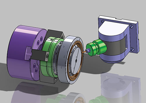
Cogitic uses a universal angle head on this turning center that can be positioned in various angles about one rotational plane. Parametric programming similar to that used for the right-angle head enables the position of the tooltip to be determined. Tool measurement probes are used to automatically determine that offset.
In January 2015, Cogitic added a DMC 125FD universal machine from DMG MORI that has a B-axis milling head and the capability to perform milling and turning operations. Depending on the job, the shop might have the flexibility to machine parts on this machine or on the Toyoda with the right-angle head.


There are a variety of ways to increase the flexibility and capability of a three-axis machine tool. One is to use angle heads, which can enable horizontal and angular milling and drilling without requiring the workpiece to be repositioned for a secondary operation.
Cogitic Corp. in Colorado Springs, Colorado, recognized the advantages of these auxiliary machine tool accessories some years ago. It currently uses a right-angle head on one of its VMCs, sometimes in conjunction with a fourth-axis rotary table, to complete multiple operations in one setup on parts in materials including titanium, Inconel and Waspalloy. The shop also realizes similar advantages using a universal angle head on one of its turning centers.


Jared Veteto, shop co-owner, says the investment in these angle heads has enabled Cogitic to be more effective and productive in machining the tough parts that flow through the shop, many for the U.S. Navy. However, he points to three aspects of using these machine tool accessories that, based on Cogitic’s experience integrating them into its processes, shops considering them should keep in mind.
First, you’ll likely need a new postprocessor. Second, you’ll have to develop a programming strategy to automatically accommodate tools of varying lengths that will be used in the heads. And third, you’ll find that on-machine probing is a complementary capability that will speed and simplify the use of the heads.
Mr. Veteto says the benefits of angle heads make addressing any initial challenges worth it, especially for shops that can’t currently justify the purchase of a high-end five-axis machine, as he explained during a visit to the shop located near the base of the Southern Rocky Mountains.
Angling for Success
Cogitic’s other co-owner is Mr. Veteto’s brother, Jonathan, who is in charge of the shop’s quality department. This shop is the brothers’ third business together. The first was a production machine shop, and their second was a materials engineering company with a focus on advanced ceramics. When things slowed for the engineering company, the brothers decided to get back into machining, this time specifically targeting markets with significant barriers to entry.
The shop found its first opportunity in the Navy’s nuclear program, which currently represents two-thirds of its business. Cogitic (meaning “forward thought and motion”) machines repair/replacement parts such as nuclear reactors and submarine pressure boundary components in the tricky materials mentioned earlier. In fact, it is one of only 30 or so small businesses approved to perform this type of work directly for the Navy.
One of the parts that spurred the shop to consider an angle head was an Inconel seal ring with multiple threaded holes about its periphery. The thought was to use the head in conjunction with a Tsudakoma fourth-axis rotary table installed with its back on the table of a Toyoda FV1365 VMC to provide C-axis rotation.
The shop consulted with BIG KAISER to determine an appropriate angle head for this application. The model it chose was an AG90 right-angle head with a fixed 90-degree, 3,000-rpm spindle that can rotate a full 360 degrees parallel to the VMC’s table. The head has a locating pin that engages with a stop block mounted to the spindle to prevent radial head movement during operation. This model is referred to as a “built-up” version, meaning it has a short taper for quick changing of various adapters for tools such as end mills, shell mills, taps and so on. It also features a rigid Big-Plus dual-contact spindle interface, meaning the tapers and faces of the angle head and spindle contact fully and simultaneously when clamped. (The angle head’s built-up taper and adapters have that same interface, and the significance of this will be highlighted later.)
There were a few hurdles to clear in order to perform the type of work the shop wanted to with this setup. In order to perform thread milling and accommodate interpolating motion for contouring work in conjunction with the fourth-axis table, the shop had to get a new postprocessor. Mr. Veteto says this took a couple months of back and forth with its postprocessor developer followed by subsequent proving-out to complete.
The next issue involved programming. More specifically, it required ensuring that the machine knew exactly where the tip of a tool installed in the angle head was located.
Mr. Veteto believes this might not have been an issue if the shop was using only one tool of a given length in the head. That would likely be a matter of simply measuring the tool length in the X axis and adding that information into the part program (although the angle head can rotate 360 degrees, the shop typically uses it with tools oriented in the X axis). However, whenever a tool of a different length was to be used, the program would have to be modified with that new tool length and re-posted. The shop didn’t want to have to do that, knowing that most of its jobs would call for various tools of various lengths.
Joe Wells, senior manufacturing engineer, developed a solution by using the Macro B parametric programming capability of the VMC’s FANUC 0i-MD CNC and taking advantage of the flush contact between the faces of the angle head and tool adapters.
As shown in the CAD model above, the face of the angle head is co-planar with the machine spindle centerline. Therefore, the measured length of the tool installed in its adapter is the distance the tooltip extends out from the spindle centerline in the X axis.
In order to enable the program to automatically handle multiple tool lengths, Mr. Wells created a couple of lines of Macro B code to generate a temporary global shift in the X axis depending on the length of the tool to be used. This is similar to what’s done to accommodate different tool lengths in a VMC’s Z axis, whereby the CNC pulls each tool’s length from a register and performs the offset automatically. However, it’s not possible to do this for the different tools extending out of the angle head in the VMC’s X axis, which is why the lines of Macro B codes are required.
Mr. Wells explains that when a new tool is to be used in the right-angle head, a line of Macro B code resets the X-axis offset to nominal (i.e. the location of the spindle centerline). A second line of code then pulls the value for the length of the new tool from a register to establish the temporary X-axis shift. Operators input the offset values for angle-head tools into the register when setting up a new job that will use the head. (A presetter is used to measure the length of those tools offline.) This enables the part program to run continuously regardless of how many tools are required for the head.
Cogitic also uses a universal angle head on its NLX turning center from DMG MORI. This head can position a tool at a variety of angles, but rotates in only one plane. A temporary global shift is performed for each tool similarly to what’s done on the VMC for the right-angle head. The turning center has tool measurement probes for both the main and subspindle, so those tools can be automatically touched-off during setup to determine the offset. Like any other attachment used on a turning center, it’s important to ensure there’s sufficient clearance between the universal angle head, and tools or attachments in nearby turret stations.
Next Logical Addition
In January, Cogitic added a big DMC 125FD universal machine from DMG MORI that has a B-axis milling head and the capability to perform milling and turning operations. Although this machine can produce parts faster than the VMC with the right-angle head, the VMC remains a viable option for machining those parts when the bigger machine is unavailable. Although efficiency is important, throughput is sometimes more vital.
That said, it’s important to realize that an angle head is a spindle attachment, not a direct output from a machine’s spindle. Because the head’s rigidity and horsepower are limited, cutting passes should be taken with lighter chip loads and cutting depths. In fact, Mr. Veteto recommends that potential angle head buyers first describe to the accessory manufacturer how they plan to use the heads to ensure that an angle head is indeed appropriate for a given part geometry and material, and, if it is, that the proper style of head is identified.


Related Content

Choosing The Right Grinding Wheel
Understanding grinding wheel fundamentals will help you choose the right wheel for the job.
Read More
Volumetric Accuracy Is Key to Machining James Webb Telescope
To meet the extreme tolerance of the telescope’s beryllium mirrors, the manufacturer had to rely on stable horizontal machining centers with a high degree of consistency volumetric accuracy.
Read More
How to Reduce Cycle Times by 70% and More on Your Existing CNCs and Dramatically Improve Tool Life Too
By employing advanced high efficiency milling techniques for the entire machining routine, SolidCAM’s iMachining technology can drastically reduce cycle times while vastly improving tool life compared to traditional milling.
Read More
Threading On A Lathe
The right choices in tooling and technique can optimize the thread turning process.
Read MoreRead Next

The Cut Scene: The Finer Details of Large-Format Machining
Small details and features can have an outsized impact on large parts, such as Barbco’s collapsible utility drill head.
Read More

3 Mistakes That Cause CNC Programs to Fail
Despite enhancements to manufacturing technology, there are still issues today that can cause programs to fail. These failures can cause lost time, scrapped parts, damaged machines and even injured operators.
Read More