
Dial vs. Test Indicators
Dial and test indicators are close cousins. They are both mechanical magnifying devices used for dimensional comparison.

If Angle A is 5 degrees, the correction factor is 0.996; if angle A is 10 degrees, the correction factor is 0.985; if angle A is 15 degrees, the correction factor is 0.965.


Although dial and test indicators share many similarities, test indicators are distinct from dial indicators. The immediately obvious difference is that test indicators have lever-type contacts and tend to be smaller and lighter than dial indicators. In general, the two tools are used in different applications: Test indicators are utilized for layout work on surface plates or aiding in part setup during the machining process while dial indicators are used for comparative measurements with gages and fixtures.
While both dial and test indicators are mainly comparative devices, test indicators excel at consistency measurements, as opposed to comparative ones. They are most often used to explore relatively broad part surfaces in either one or two dimensions, for example, measuring variations in height, flatness and roundness. Typical setup includes mounting the test indicator to a height stand on the surface plate and moving either the workpiece or the stand freely on the plate.


When combined with a V block or a pair of centers, test indicators are used to test for roundness or runout on cylindrical parts. The angular motion of the test indicator's lever enables the contact to ride easily over irregularities on part surfaces. This capability is lacking in dial indicators because the vertical-action plunger may resist responding to surface irregularities pushing sideways against the contact.
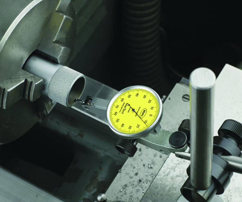
The ability to ride over irregular surfaces also makes test indicators well suited for use in machine setups, particularly on lathes, but also on jig bores. The indicator is held by an articulated test stand, usually mounted right on the machine. The operator brings the indicator into rough contact with the chucked blank, then turns the spindle to obtain a very quick reading on runout. No mastering is required when checking roundness, runout or flatness. The user simply brings the indicator close to the part surface, pushes down on the lever to make contact with the part and rotates the indicator's bezel to zero.
Furthermore, test indicators can be oriented more flexibly relative to the workpiece than dial indicators, as dials can be mounted on the top, side or end for easier viewing. The narrow lever and very small contact ball also fit readily into many places that dial indicators cannot reach, except with special attachments.
Test indicators generally have higher resolution and a shorter range of measurement. Typical resolution (least grad) for test indicators is 0.0001 to 0.00005 inch (0.01 to 0.001 mm) with measurement range being between ±0.004 and ±0.015 inch (±0.04 and ±0.025 mm). Test indicators enable only a single revolution of the pointer around the dial, and test indicator pointers always travel clockwise. The dials are balanced, meaning that the numbers keep ascending in both directions from zero.
The probes are a very important part of the test indicator since they achieve magnification with levers and gears. Thus, it is critical to use the proper length contact. Using a contact point with a length other that its original will change the magnification, resulting in incorrect readings. Test indicators are available in models with short or long contacts to increase versatility, and the contact length is often marked on the indicator’s case as a way to remind the user of the proper contact to use.
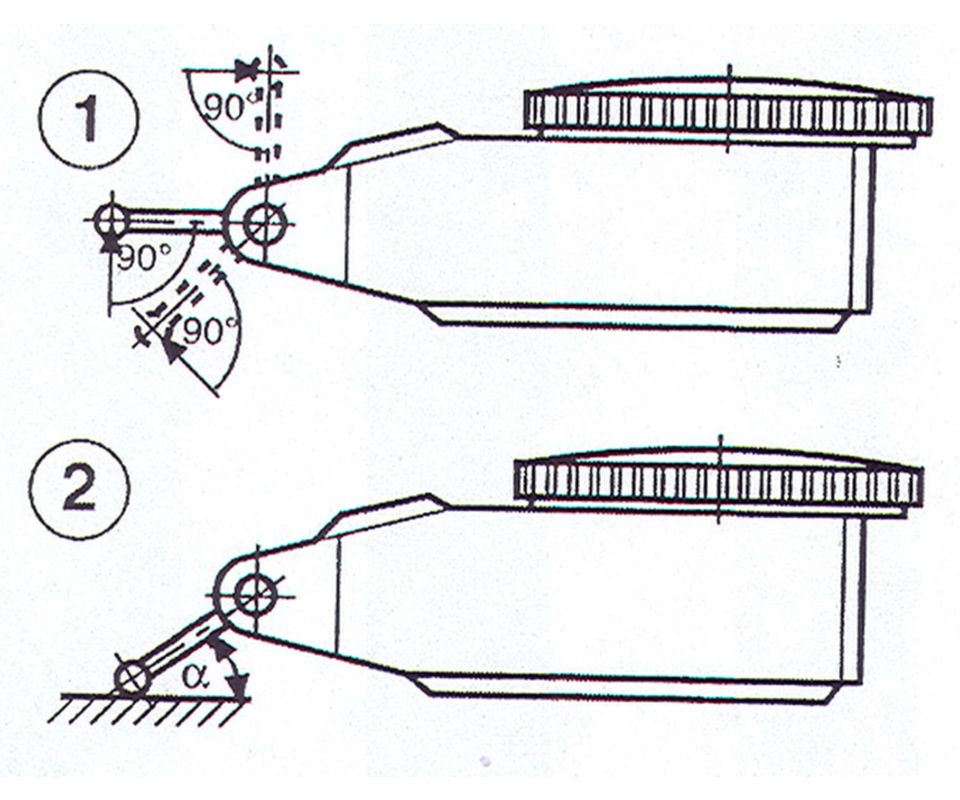
Cosign error can be an issue with test-style indicators when performing any length-variation measurement. With a test-style indicator, accuracy is greatest when the axis of the contact point is perpendicular to the measuring direction (see figure). This is seldom the case, however, and as the angle of the contact to the surface increases, the amount of vertical distance encompassed (change in height) also increases. The result is cosign error. Tables such as below help to correct for this error, where A is the angle between the probe and the surface of the part.
In circumstances in which a larger cosign error exists, such as when the angle of the probe is greater than 30 degrees, it may be better to zero the comparator closer to the actual part size. This will minimize the cosign error in the reading. To do this, select a zero master that is closer to the calculated reading than the actual standard size.
In general, the rule is to always try to maintain the probe angle to within ±15 degrees in either direction. There are also special contacts available that help minimize this type of error with a special involute shape manufactured into the contact.
Test indicators are extremely useful little items that are the family of choice when versatility with surface-plate inspection is needed.


Related Content

A Case for Combining Workholding with Optical Scanning
Automotive dies and die inserts are often complex, one-off parts with little room for error. Integrity Tool's investments in modular workholding tools and 3D optical scanning have allowed the company to create niche capabilities for its CNC machined parts.
Read More
Building an Automation Solution From the Ground Up
IMTS 2022 provides visitors the opportunity to meet with product experts to design automation solutions from scratch.
Read More
What Should Machinists Know About In-Machine Probing?
In-machine probing doesn’t reach the power of CMMs but can still be useful for pre- and mid-process control, as well as for “rough screening” of parts.
Read More
5 Things CNC Operators Must Know About Sizing Adjustments
For CNC operators, sizing adjustment is an essential skill. Keep these points in mind when training new CNC users.
Read MoreRead Next

The Cut Scene: The Finer Details of Large-Format Machining
Small details and features can have an outsized impact on large parts, such as Barbco’s collapsible utility drill head.
Read More

3 Mistakes That Cause CNC Programs to Fail
Despite enhancements to manufacturing technology, there are still issues today that can cause programs to fail. These failures can cause lost time, scrapped parts, damaged machines and even injured operators.
Read More