
Grind to Finish: A Postprocessing Solution for Additive Manufacturing
3D printed metal parts typically feature little stock remaining for finishing. Grinding is potentially an effective solution for meeting final tolerances. An abrasive technology provider investigates grinding as a complement to AM.
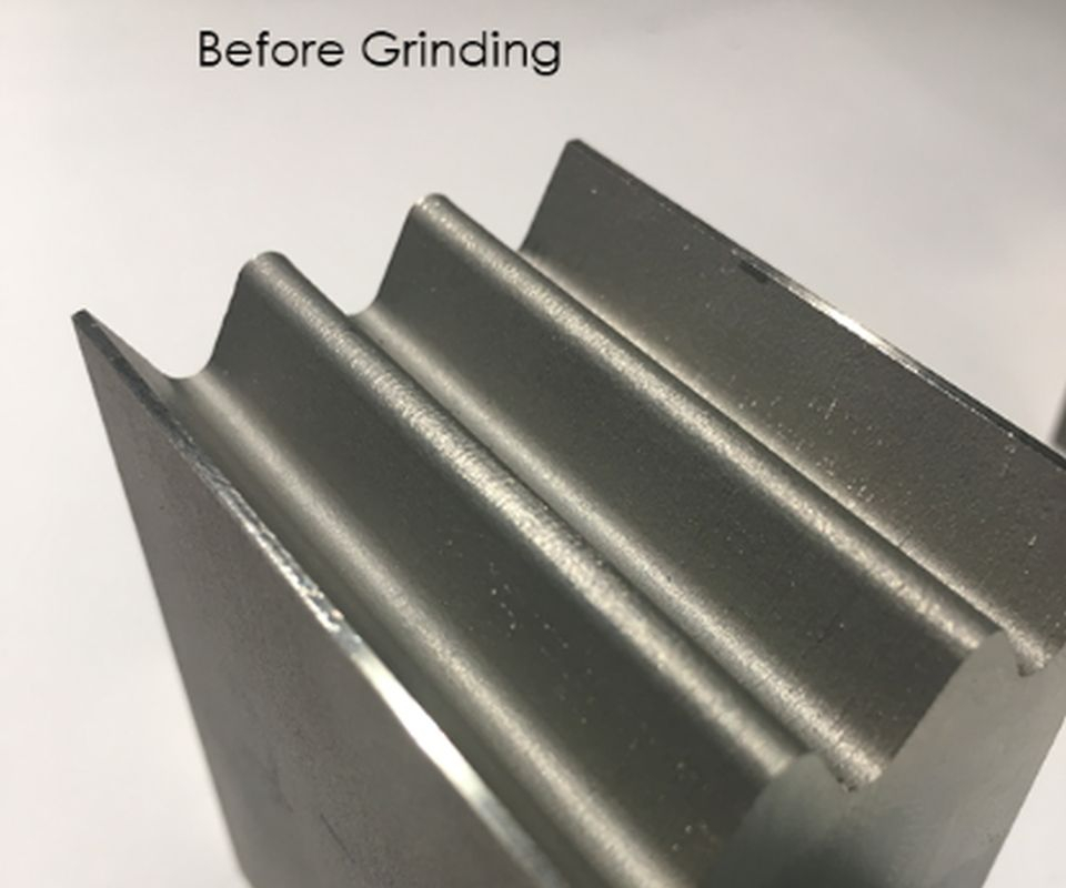
Fig. 1: AM Inconel 718 test specimen before grinding
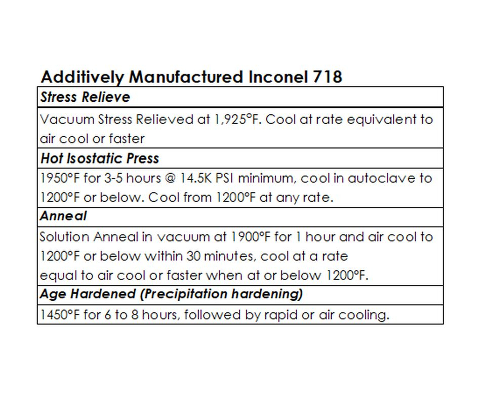
Table 1: Processing and heat treatment of AM Inconel 718 specimens
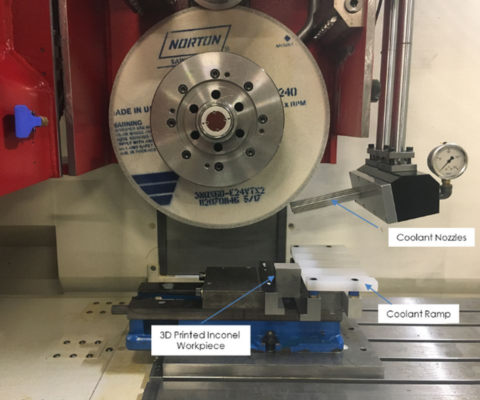
Fig. 2: Overall machine setup

Fig. 3: Close-up of machine
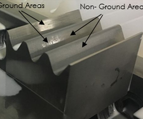
Fig. 4: Partially ground AM Inconel 718 specimen
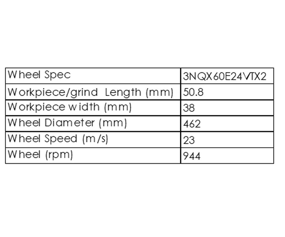
Table 2: Test Details
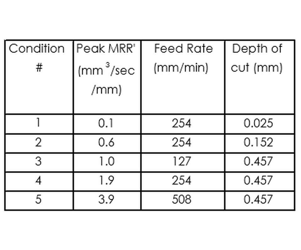
Table 3: Grinding Conditions

Fig. 5a: Surface finish measurement directions (measured parallel to the grind direction)
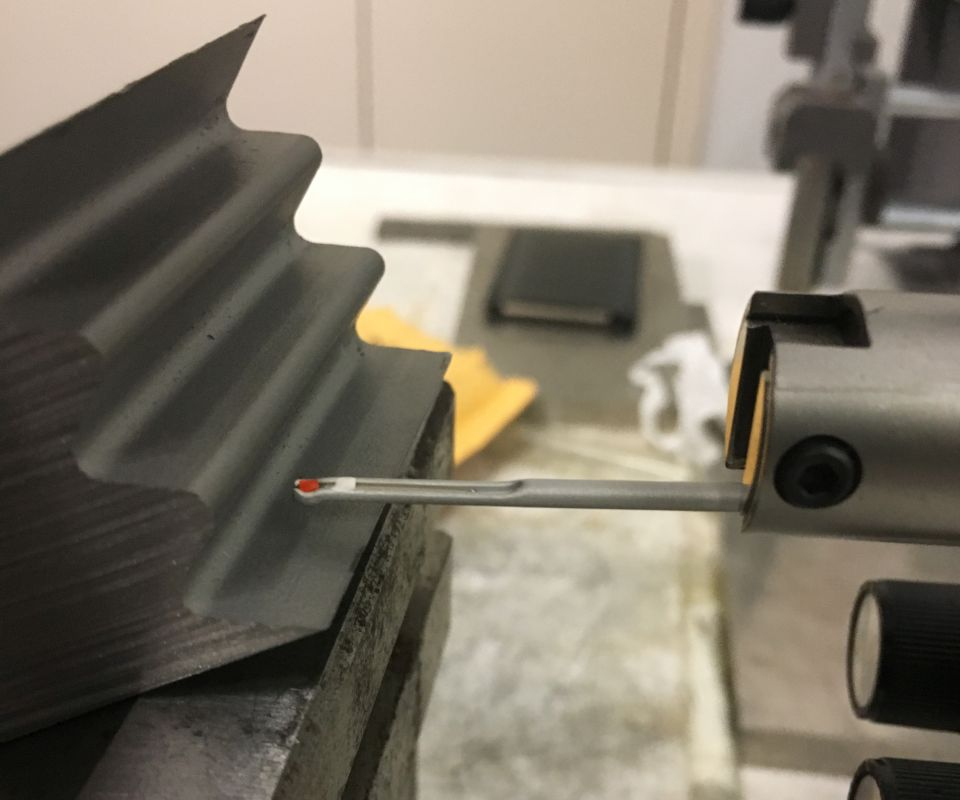
Fig. 5b: Surface finish measurement directions (measured perpendicular to the grind direction)
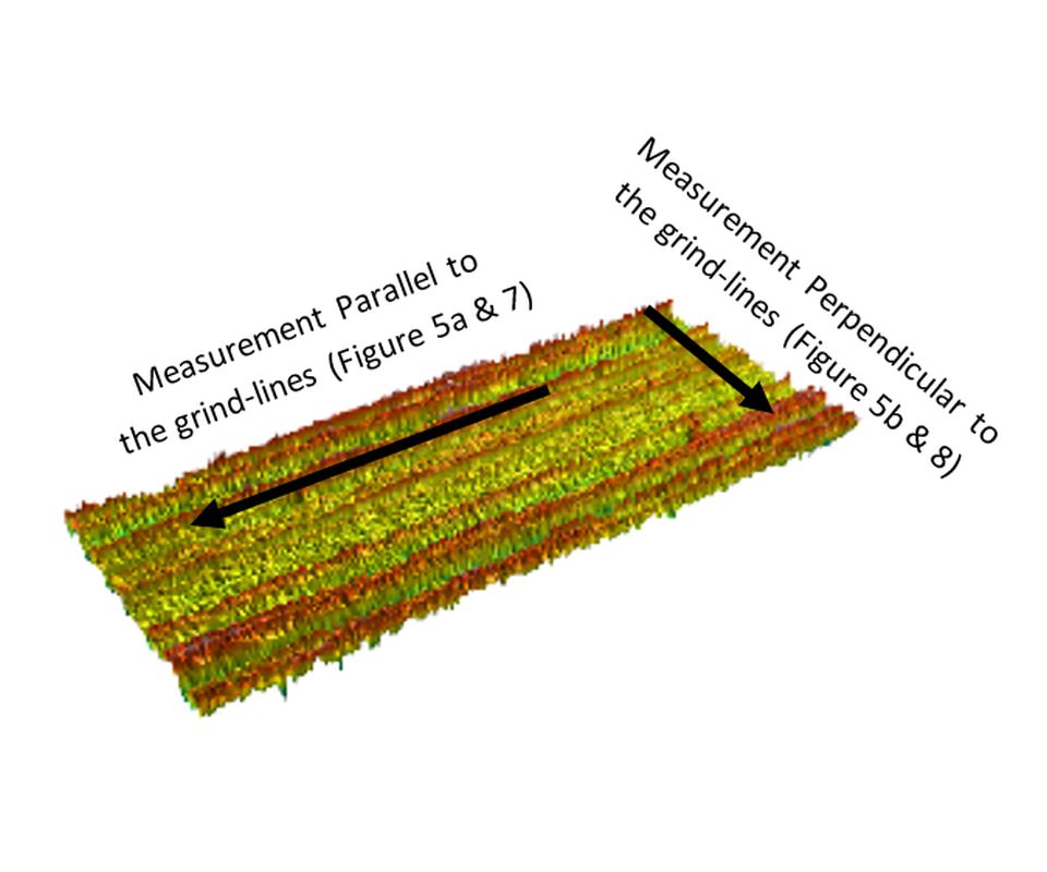
Fig. 6: 3D surface scan of ground surface
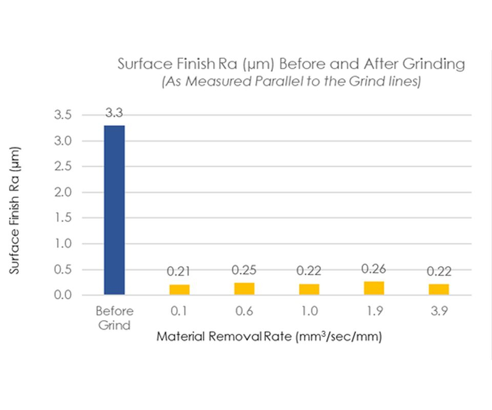
Fig. 7: Surface finish-Ra in microns (parallel to grind direction) before and after grinding
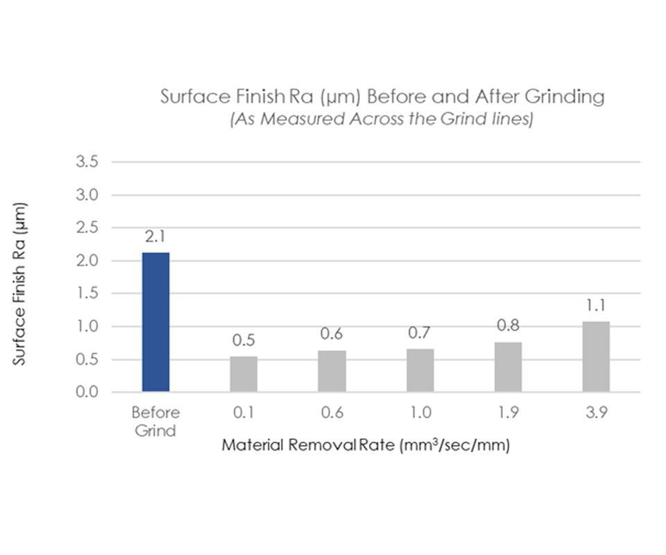
Fig. 8: Surface finish-Ra in microns (perpendicular to grind direction) before and after grinding
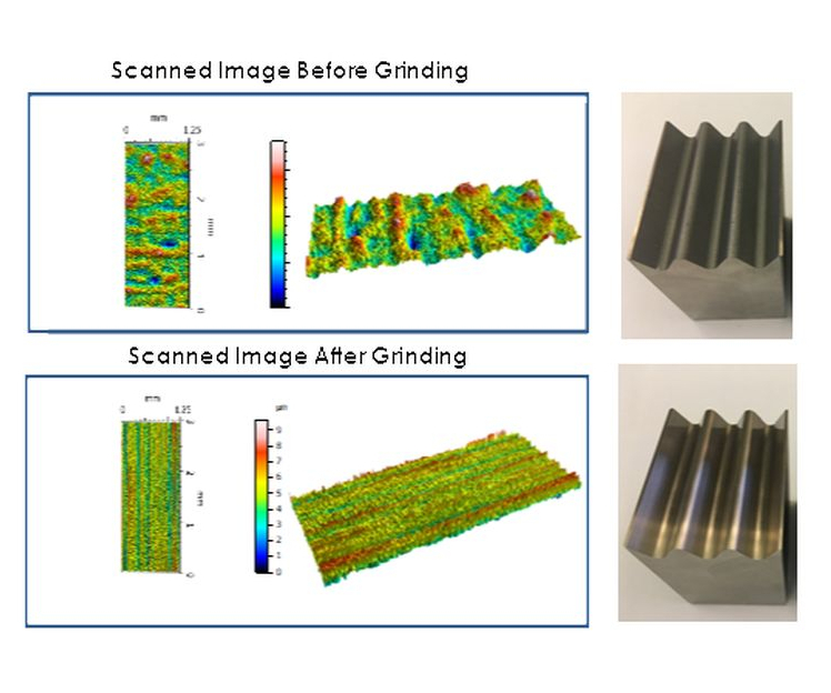
Fig. 9: 3D surface scan of AM Inconel 718 specimen in the “as-received” and “after-grind” condition
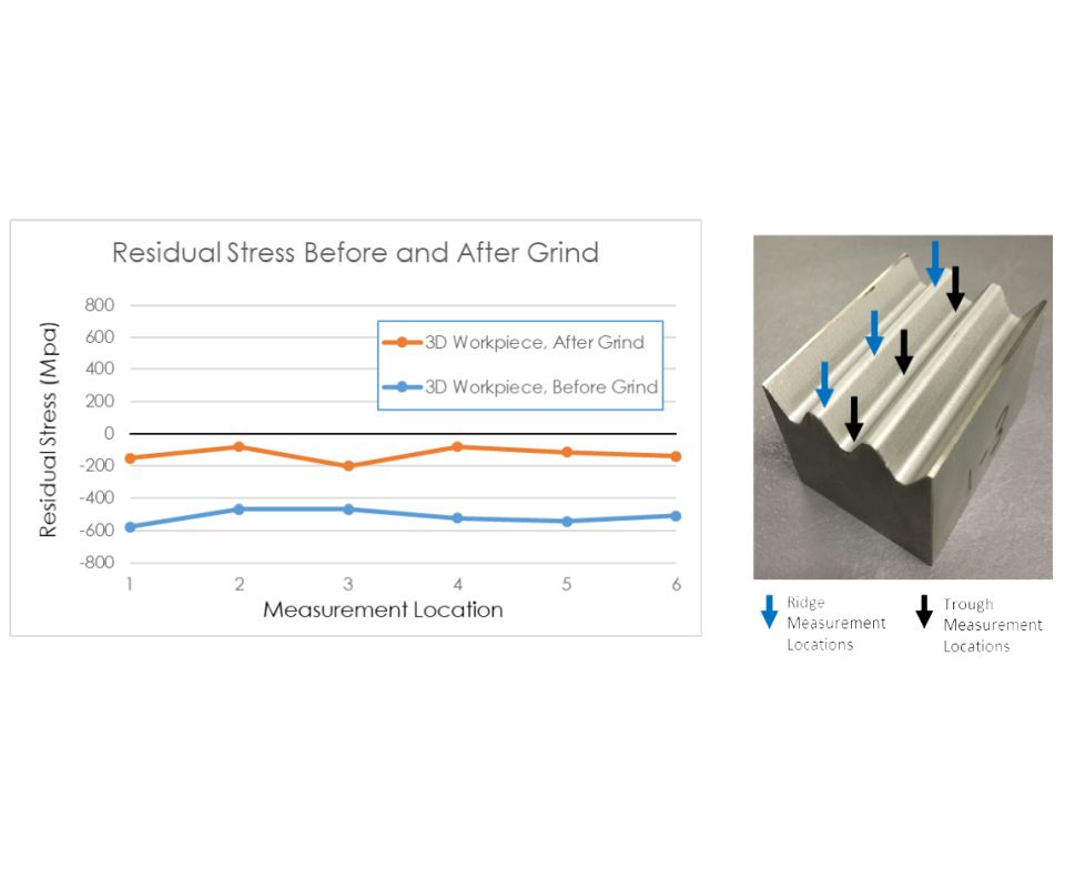
Fig. 10: Comparison of the surface residual stress measurement of AM Inconel 718 specimen in the “as-received” and “after-grind” condition
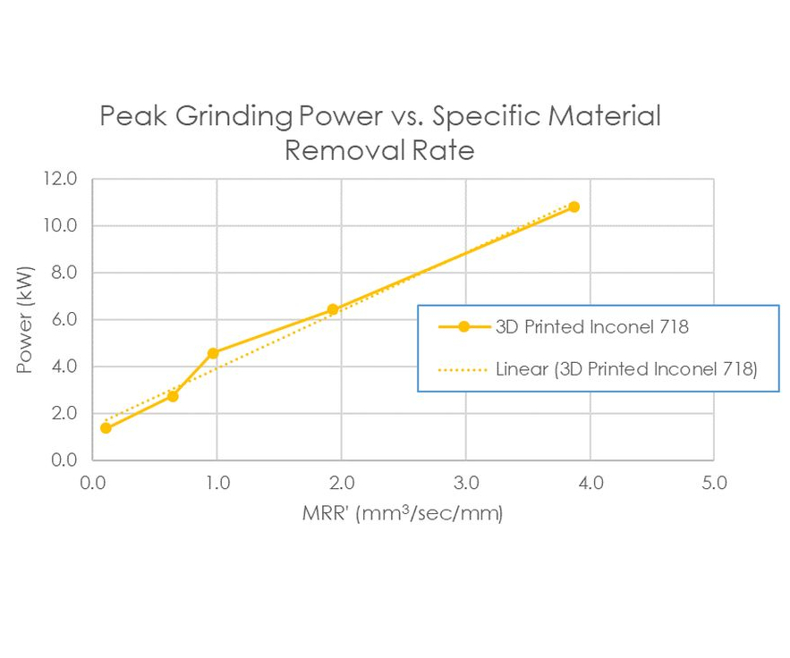
Fig. 11: Grinding power


The increased use of additive manufacturing (AM) in the aerospace and medical markets fosters a growing need to finish the surfaces of additive parts to meet final application requirements. Since the additive manufacturing process is capable of producing components close to near-net shape, there is often little stock that remains for providing final finish. This benefits the overall manufacturing process by reducing waste, but it also means that subsequent finishing processes have limited room for postprocessing errors and inconsistencies. Postprocessing, therefore, needs to be consistent in achieving part tolerances and surface quality. This article will demonstrate that grinding offers an effective option with additive manufacturing when close tolerances and finer finishes are required. When compared with other traditional material removal processes such as milling and turning, grinding typically offers the best surface quality and surface integrity characteristics. In order to gain more insight into finishing for additive manufacturing specifically as it might apply to nickel-based superalloy components used in aerospace, engineers at Norton | Saint-Gobain conducted a finish grinding study on Inconel 718 specimens made additively. The engineers were seeking answers to three pertinent questions:
- What is the minimum stock/volume that needs to be ground off an additively manufactured component?
- What range of surface finishes can be obtained from grinding an additively manufactured component with the latest generation of abrasive grinding wheels?
- What, if any, is the impact on surface residual stresses on an AM component after finish grinding?
AM IN718 specimens manufactured using the direct metal laser sintering (DMLS) process were obtained from Stratasys Direct Manufacturing. Figure 1 shows an image of the AM test specimen. After additive manufacturing, these specimens were media blasted and went through stress relief, hot isostatic pressing, solution treatment/anneal and precipitation hardening. Table 1 shows the heat treatment parameters used. The hardness of the specimens measured 40 HRC. The specimens were then ground using a Norton NQX60E24VTX2 grinding wheel on a Magerle MFP-125.50.65 creep-feed grinder located at the Norton | Saint-Gobain Higgins Grinding Technology Center. Figures 2 and 3 show a picture of the test setup.


First, several areas were ground at progressively increasing depths of cut to determine the minimum stock that needs to be removed to clean up an additively manufactured surface. After each grind at a specific depth of cut, the surfaces were looked at for the presence of visual imperfections. Figure 4 shows an image of the specimen that is partially cleaned during this sequence of trials. The trial results determined that in order to eliminate any geometrical inconsistencies and surface imperfections related to the additive manufacturing process, approximately 0.30 to 0.45 mm of stock needs to be removed from the component.
For this test, the grind length was 50.8 mm, and the wheel diameter was 462 mm, operating at 23 m/sec. (see Table 2). Tables 2 and 3 document test details and grinding conditions used in the study. A total of five specific material removal rates (MRRs) were tested ranging from 0.1 mm3/sec./mm to 3.9 mm3/sec./mm (see Table 3). The MRR was adjusted by altering the feed rate (mm/min.) or the depth of cut (mm). Multiple material removal rates were tested in order to evaluate the effect of low to medium MRRs on surface finish and grinding power. While nickel-based alloys such as Inconel 718 can be ground at high removal rates using modern engineered abrasives, the MRRs selected in this study were lower, based on the typical finishing rates used in industrial processes now to finish standard Inconel workpieces. Based on the grinding of standard (non-AM) workpieces, the expected results were that as MRR increased, surface finishes (Ra) of ground workpieces would increase or get coarser, as grinding power increased.
The surface finishes of the workpieces were measured before and after grinding using a Federal Contact profilometer system 5000. Measurements were taken at several locations and in two directions on the workpiece (Figures 5a and 5b). Non-contact profilometer surface measurements were also taken in multiple locations (Figure 6).
An evaluation of the surface finish on the AM material before grinding found it to be considerably different depending on the direction of measurement (as shown when comparing Figures 7 and 8). When measured lengthwise (Figure 5a), the average finish was 3.3 microns Ra and when measured widthwise (Figure 5b), the average finish was 2.1 microns Ra. This large difference would not typically be observed when measuring a standard, as-cast Inconel 718 material. This appears to be related to the 3D manufacturing method, but the exact reason is unknown at this time.
The conventional method of using a contact profilometer to measurie a ground surface finish takes the trace perpendicular to the grind lines as opposed to measuring parallel to the grind lines. This study measured the surface finish in both parallel and perpendicular directions to the grind lines. The after-grind results were then compared to the before grind lengthwise and widthwise measurements, as shown in Figure 7 and 8.
It is important to understand that when measuring a ground surface in a perpendicular direction to the grind lines, the stylus travels over the peaks and valleys of the grind lines. Whereas when measuring in the parallel direction the stylus moves parallel to the grind lines never crossing over the peaks and valleys (Figure 6). Therefore, perpendicular measurements taken in this study had significantly higher (coarser) surface finish results as compared to measurements taken in a parallel direction, as would be expected (Figures 7 and 8).
An evaluation of the surface finish on the AM material before grinding versus after grinding found that grinding improved the surface finish significantly. This was true for measurements in both the parallel and perpendicular directions. When measuring in a parallel direction, the average surface finish was 3.3 microns Ra before grinding and 0.21 microns Ra after grinding (Figure 7). When measuring perpendicular to the grind direction the surface finish was an average of 2.1 microns Ra before grinding, and as low as 0.5 microns Ra after grinding (Figure 8).
Additive specimens were also analyzed using a Nanovea 3D surface profilometer, white light chromatic aberration technique, to obtain a visual representation of the surface features. Figure 9 is a 3D surface plot of the AM specimen taken before grinding, in the “as-received” condition, and after grinding. For this test, the AM specimen in the “as-received” condition was media blasted with glass media to take off the high peaks from the surface. The lines that are visible on the surface plot taken after grinding are lay lines from the grinding operation. Grinding wheels with finer abrasive grains or other abrasive products, such as engineered abrasive belts, can be used to reduce the lay lines further and generate a super-finished surface if that is a critical requirement to the component’s performance and quality.
In order to understand the impact of grinding on the overall surface integrity of the AM IN718 specimen, surface residual stresses of the AM specimens were measured using Bruker-AXS D8 Discover microdiffraction equipment in the “as received” condition as well as after grinding. A comparison of the measurements taken in both conditions at six different locations on the same specimen (Figure 10) proves that near-surface residual stresses are negative/compressive in both the “as-received” and “after-grind” condition. This is typical of components after finish grinding, where near-surface residual stresses are found to be compressive in nature, an effect that tends to help fatigue life by retarding surface crack propagation.
Grinding power was measured for all five material removal rates tested in this study. Figure 11 shows that as the MRR is increased, the grinding power also increases. This behavior is typical of most grinding operations. At the lowest rate of 0.1 mm3/sec./mm, the peak power draw during the grind was 1.4 kW. At the highest material removal rate of 3.9 mm3/sec./mm, the grinding power was 10.8 kW.
The results of this study proved that finish grinding of additively manufactured, nickel-based superalloys, such as Inconel 718, can be successfully employed to achieve a reduction in surface roughness of approximately 94 percent when measured parallel to the grind lines and approximately 34 percent when measured perpendicular to the grind lines. Grinding wheels with finer abrasive grains or other abrasive products, such as engineered abrasive belts, can be used to generate a super-finished surface if required. It also showed that approximately 0.30 to 0.45 mm of stock needs to be removed from the component to generate improved surface finishes and clean up any geometrical inconsistencies related to the 3D manufacturing process. The minimal stock requirement is critical information for additive manufacturers as they strive to make AM components as close to near-net shape as possible to be cost-effective. Moreover, the residual stress data showed that the surface stresses after grinding were compressive in nature, indicating a beneficial impact on retarding surface crack propagation and thereby extending the fatigue life of manufactured components.


Related Content

Additive/Subtractive Hybrid CNC Machine Tools Continue to Make Gains (Includes Video)
The hybrid machine tool is an idea that continues to advance. Two important developments of recent years expand the possibilities for this platform.
Read More
The Cool Parts Showcase Seeks Innovative 3D Printed Parts
Do you solve problems with 3D printing? Enter your 3D printed parts in this contest from The Cool Parts Show.
Read More
5 Tips for Getting the Most From the Historic Return of North America’s Biggest Manufacturing Event
Plan. Explore. Think of the future. And oh yeah, the shoes. Here is how to get the most from the major manufacturing event that none of us have experienced in four years, and that many will be experiencing for the first time.
Read More
In Moldmaking, Mantle Process Addresses Lead Time and Talent Pool
A new process delivered through what looks like a standard machining center promises to streamline machining of injection mold cores and cavities and even answer the declining availability of toolmakers.
Read MoreRead Next

3 Mistakes That Cause CNC Programs to Fail
Despite enhancements to manufacturing technology, there are still issues today that can cause programs to fail. These failures can cause lost time, scrapped parts, damaged machines and even injured operators.
Read More

The Cut Scene: The Finer Details of Large-Format Machining
Small details and features can have an outsized impact on large parts, such as Barbco’s collapsible utility drill head.
Read More