Gage calibration is a routine process followed by most precision gage users. A step-by-step documentation procedure defines how regularly a gage should be checked and how its performance should be documented.
Surface finish roughness instruments use a roughness specimen, or “patch,” that is certified for a known wave form to provide a specific surface parameter result. With this certified specimen in hand, it is easy to verify that the surface finish measuring instrument is reading properly. However, probes are sensitive and are often used in harsh environments, so it is not uncommon for users to check the performance of surface finish gages at the start of each shift or even between measurements.
What’s really being checked is the gain, or magnification, of the probe as it goes through its measuring range. For most applications, a typical surface finish standard has an Ra value of 118 microinches (3 microns).
Surface finish measurements have moved out to the shop floor, so the reference specimen should be monitored closely. The calibration artifact should always be kept clean and dry to ensure that dirt and debris do not affect the results.
Over time, it is not uncommon to see the surface finish instrument’s displayed results fail to coincide with the certified values of the roughness standard during calibration. Erroneous results can be interpreted as a fault with the measurement amplifier or the measurement probe (heaven forbid), but this is rarely the case. The most common cause is a “dirty” roughness patch.
Most roughness standards have a triangular wave-form pattern with sharp corners, so it is easy for debris to collect on the valley areas. Contaminants such as dust, powdered metal, oil, dried coolant and others can greatly affect the measurement results. Even in tiny amounts, such debris can prevent the measurement probe from getting down into the valleys on the roughness standard. Debris can affect measurement on the peaks, as well.
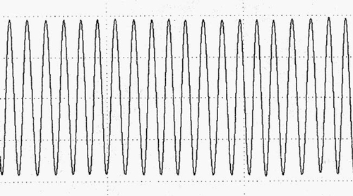
Figures 1 and 2 above are printed profiles of certified triangular roughness specimens. Figure 1 is a new, clean roughness specimen with an Ra value of 2.993 microns. Notice the perfect sinusoidal-type wave form over the whole length of the profile.
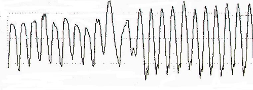
Figure 2 shows a measurement using the same surface roughness gage but on a patch that has been out on the shop floor for a number of months. Notice the inconsistency of the measured values, and that the peaks and valleys are not consistent across the profile length. This is particularly noticeable on valleys at the beginning of the profile and is typical of debris in the valleys of the roughness standard that prevent the measurement probe from reaching the bottom of the profile.
Roughness standards may look clean to the naked eye, but the dirt and debris typically measure 2 to 10 microns. Therefore, most of it cannot be seen, but it is present nonetheless.
To clean a roughness artifact, use cotton swabs, acetone (denatured alcohol for plastic roughness standards) and the surface finish measurement instrument itself, with profile-printout capability. The instrument is just as important as the acetone and swabs because its magnification capability is significantly greater than the human eye, and measurement results can be demonstrated with a printed profile of the measured surface.
Roughness standards should be handled with care to prevent scratches on the surfaces. Here’s a step-by-step procedure:
• Take a measurement on the roughness artifact, and print out the measured profile. If the profile looks similar to Figure 2, chances are dirt has likely accumulated in the valley areas of the roughness standard.
• Saturate the end of the swab with acetone. Using medium force, wipe the surface parallel to the direction of the lay pattern on the standard—not perpendicular. Measurements are performed perpendicular to the lay pattern; cleaning should be done in a parallel direction.
• Take a second measurement and reprint the measured profile. The measurement results will demonstrate a more consistent wave form in the profile. Again, the profile should be consistent through the whole length of the trace.
It may be necessary to perform these steps repeatedly because dirt can be stubborn. When cleaning, make sure that nothing other than the swab tip comes in contact with the roughness standard.