Holes Big Enough To Fall Into
Maybe you’re not in Texas, but suddenly you find yourself faced with a huge measurement requirement. You’ve been given the task of checking some large diameters—not your 6 inch variety—I mean those large enough to drive a herd of cows through.
Maybe you’re not in Texas, but suddenly you find yourself faced with a huge measurement requirement. You’ve been given the task of checking some large diameters—not your 6 inch variety—I mean those large enough to drive a herd of cows through. You know, the 12 inch, 36 inch or even the 80 inch variety.
Don’t go for the tequila yet. There are lots of choices available to meet this challenge, which boils down to selecting the right tool for the application. The first step is to look at the part print, determine the measurement tolerances and see if there are any callouts for out-of-round conditions. This information will lead you to the best tool for the job.
If the tolerance is loose—within 0.01 inch—then a digital or vernier caliper-style gage will provide a good fast check of the part diameter. Just make sure the jaws are square to the part and placed to find the major diameter. On the larger diameters, this could even be a two-person operation.
An inside micrometer is another alternative. Special kits make it possible to assemble a series of calibrated extension rods to span any diameter. Because this is a true point-to-point measuring system, the diameter has to be found by rocking the gage both axially and radially. On a large bore, this may require one operator holding the reference side of the gage in place while the second operator “searches” for the maximum diameter.
Tighter tolerances call for different types of gages. Some adjustable bore gages can get to these larger sizes. They deliver improved accuracy and repeatability because they 1) are adjusted to a specific (in this case large) size range; 2) provide comparative measurements using a master; and 3) are often equipped with a centralizer which makes it easy to “search” for the diameter. Pair this gage with a good digital indicator that includes a dynamic function to store the maximum size, and you have a great tool for fast, repetitive readings.
Gages with beams that have reference and sensing contacts mounted on either end are another comparative tool. In addition to satisfying large diameter measurement requirements for tolerances within 0.001 inch, beam type gages have standard rest pad and contact combinations that allow measurement of shallow bores and thin wall parts, as well as grooves and other features machined within the bore. You can even build up the gage to get around a central hub.
When the blueprint requires you to check not only the diameter but out-of-roundness as well, the bar has been raised. The gages mentioned above can still be used, but the process may involve making five or ten measurements on the part, recording the results, and calculating out-of-roundness according to a formula. Not only is this approach time consuming, it also magnifies operator influences on the result because so many measurements are required.
An advanced concept can be brought into play here: The better the gage is staged, the better the result of the measurement. That’s why the shallow bore gage with its two references is better than the gages that just have one reference. By the same thought process, another reference point will result in even further improvement.
Let’s take the same shallow bore gage, but this time we will use it with a staging post that centralizes both the part and the gage. The operator only has to apply a little force to make sure the reference contact is against the part, and the central post takes care of finding the maximum diameter without having to rock the part back and forth. Now it’s a breeze to inspect for out-of-round conditions.
Just rotate the gage, keeping a little force applied to the reference contact, and watch the swing of the needle, looking for the minimum and maximum values. Watching the needle, you can visually inspect for the Total Indicator Reading (TIR) or out-of-roundness variation. Add a memory to the indicator or an amplifier to store discreet points, and you can automatically calculate the average roundness.
Related Content
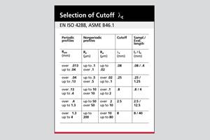
How to Choose the Right Cut Off When Measuring Roughness
Measurement results for surface finishing parameters can vary depending on the filter parameter (Lc), also known as the cutoff.
Read More5 Things CNC Operators Must Know About Sizing Adjustments
For CNC operators, sizing adjustment is an essential skill. Keep these points in mind when training new CNC users.
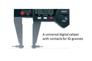
Read MoreChoosing the Correct Gage Type for Groove Inspection
Grooves play a critical functional role for seal rings and retainer rings, so good gaging practices are a must.
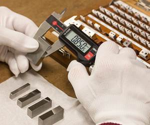
Read MoreHow To Calibrate Your Calipers
If you’re interested in calibrating your own digital, dial or Vernier calipers, here are some steps to take to make sure it goes off without a hitch.
Read MoreRead Next
The Cut Scene: The Finer Details of Large-Format Machining
Small details and features can have an outsized impact on large parts, such as Barbco’s collapsible utility drill head.
Read More3 Mistakes That Cause CNC Programs to Fail
Despite enhancements to manufacturing technology, there are still issues today that can cause programs to fail. These failures can cause lost time, scrapped parts, damaged machines and even injured operators.
Read More


