
Machining Complex Shapes
Update your methods to reap the benefits afforded by newer machines.
.jpg;width=70;height=70;mode=crop;format=webp)


Many companies use three-, four- and five-axis machining centers to machine workpieces that have complex shapes such as wing ribs, turbine blades, and almost any kind of mold core or cavity.
Traditionally, processes for complex-shape machining include programming the machine axes so the cutting tool is in the right place versus simply programming the workpiece geometry. This requires outputting a huge number of points through which the tools will move and compensating for certain cutting tool issues within the program.
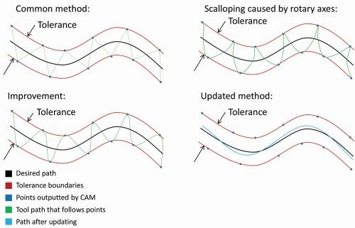
The upper left drawing in the figure above shows an example. While I have intentionally exaggerated the changes in tool path, this shows what your machines are trying to do if you use traditional methods, which are more than 20 years old.
Newer machines are capable of following true tool paths much more precisely than 20-year-old machines ever could. When you buy a new machine and apply traditional methods, workpieces often exhibit undesirable witness marks that are not experienced with older machines. This is caused by the jagged path shown in the illustration.
Unfortunately, instead of updating machining methods to take advantage of features that could make machines faster and more accurate, many companies detune, that is, desensitize axis response for the new machines to make them behave like 20-year-old machines. They may also flood programs with even more points in an attempt to keep cutting tools closer to the desired path. As a result, they will not experience any of the benefits newer machines are designed to provide. Here are a few examples of what these companies are missing:
Reduced setup time. Older machines require workpieces to be aligned with machine axes, which requires elaborate fixtures and time to align them with the machine. Newer machines can easily compensate for workpiece placement issues, so placement on the table is not nearly so critical.
No scalloping. This issue is often mistaken for a resolution improvement issue and commonly handled by detuning the machine and/or flooding programs with more points. It is related to the center of rotation in rotary axes and occurs on five-axis machines, since it is the tool path that is being programmed and not the work surface. As the rotary axis tries to provide the desired tool path, the cutter is not kept in perfect contact with the work surface. Instead, it often undercuts. Though exaggerated, the upper right drawing in the diagram illustrates this issue.
Faster motion. Consider this analogy for motion: The black line in each of the drawings represents the path that railroad engineers intend a train to follow, a smooth path that keeps it from having to slow down. In the field, obstructions along the way require workers to slightly modify the path, as the blue line in the lower right drawing illustrates. Then the engineers decide to add roads along the tracks. These roads can’t follow the same path, so the dots and green lines in the upper left drawing represent the route a car/truck will have to take.
With current CNC controls, spline interpolation allows the control to interpret the set of points provided by the CAM system as the boundaries for a spline path that the cutting tool will follow. This is represented by the blue line in the lower right drawing. While it isn’t perfect, it is well within the tolerance and closer to the intended curve than the CAM approximation at any point and allows much faster motion. So just as the train will be able to follow its tracks faster than a car could navigate the turns in a road, so can a CNC machine follow the spline path much faster than it can navigate the series of points a CAM system outputs.
Eliminated detuning. A machine cannot move very quickly if it must follow the tool path shown in the upper left drawing. This is one reason why it is detuned, which produces a tool path that looks like the one in the lower right, but it also induces greater following error. When using the modern, real-time spline look-ahead functions, the servos can be highly responsive because of the smoother path. This eliminates the need to detune and the related following error, and minimizes undesirable witness marks.
Program compatibility among machines. With traditional programming techniques, many machine-specific functions are being handled within the programs, and a program written for one machine cannot be run in another. Newer machines have compensation functions that allow workholding and cutting tool issues to be dealt with separately from the CNC program. This means you can specify part coordinates (common for all machines) instead of machine coordinates, and programs can now be shared among machines.
Simpler postprocessor maintenance. With no machine-specific issues to deal with, maintaining postprocessors will be easy. Indeed, the same program can be run on any newer machine that has the capability to machine a given part.


Read Next

3 Mistakes That Cause CNC Programs to Fail
Despite enhancements to manufacturing technology, there are still issues today that can cause programs to fail. These failures can cause lost time, scrapped parts, damaged machines and even injured operators.
Read More

The Cut Scene: The Finer Details of Large-Format Machining
Small details and features can have an outsized impact on large parts, such as Barbco’s collapsible utility drill head.
Read More